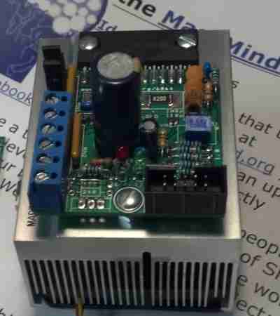
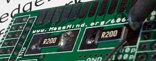
Luc's THB driver joins the other open source drivers supplied by the MassMind.org
store, adding support for BiPolar (4, 6 or 8 wire) motors up
to 4 amps/phase at 50 volts. It is based on the new THB6064AH (
Datasheet ) chip
(also known as the Toshiba
TB6564AHQ^)
which is a design improvment over the TB6560, adding support for better
microstepping, lower resonance, and protection for power on
sequence^.


* These are electronics KITs, you need to solder them together.
Features
|
The Honest Truth: It is a "chopper" type driver, so it doesn't require a terribly large heatsink, but you can expect to hear a little bit of motor "hiss" or "squeal" during operation (see the video below), and in high power systems, the motors may require more cooling than the driver. There are other drivers for different needs:
| Driver | Maximums |
Motors | Pros | Cons | ||
| Amps | Volts | Power | ||||
| Linistepper | 1 or 2, 3 max | 36 | <75 | 5, 6 or 8 wire Unipolar |
Ultra smooth, quiet, low noise, low mid band resonance, motor stays cool, cheap to repair | Limited power, driver heat |
| SLAm | 2 to 3 | 36 | 108 | 5, 6 or 8 wire Unipolar |
Stable, easy to build, small heatsink, tough | Resonance, motor heat/noise |
| THB6064 | up to 4 | 50 | 200 | 4, 6 or 8 wire Bipolar | Powerful, most motors (4, 6 or 8 wires), small heatsink, very tough | Some resonance, motor heat/noise |
| GeckoDrive.com (listed for compairison only) |
3.5-7 | 50-80 | 175-560 | Bipolar | Freaking magic | Cost $80-$166 per axis. |
Providing a range of drivers is in keeping with our "more is NOT necessarily better" approach. The same is true of motors: Unipolar motors cost less, provide less torque at low speeds, but maintain torque as speed increases. Bipolar motors, only when connected for parallel drive, provide better starting torque, but may not turn as fast and will generally be more costly. Pick the right motor for the job, based on your actual needs.
Check out working machines built by our customers, like Alan Redd who says: "I received the kits, built them, and installed them on my lathe today. I was able to follow the instructions and get both drivers put together right on the first try. I have been using a G540, and your drivers seem to have as much power and only very slightly more noise from the steppers. I am still fiddling with the power level and the decay settings, but am very happy with the performance at the current setup."
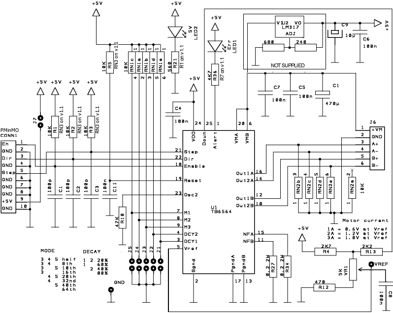
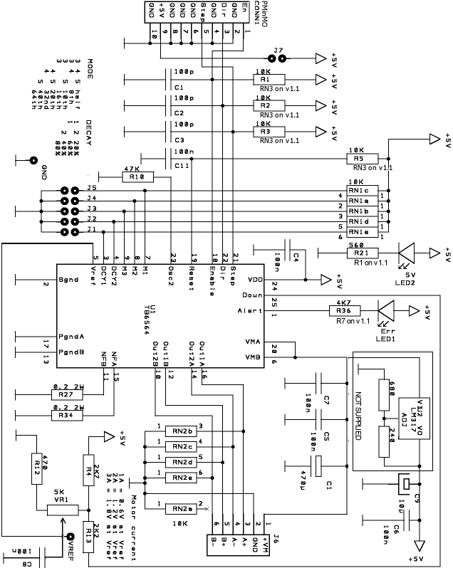
Please do NOT use the schematic to assemble the kit. Please follow the written instructions below or watch the video. If you are not an expert at soldering, PLEASE read through our soldering class first.
Version 1.2  |
Version 1.1 |
Version 1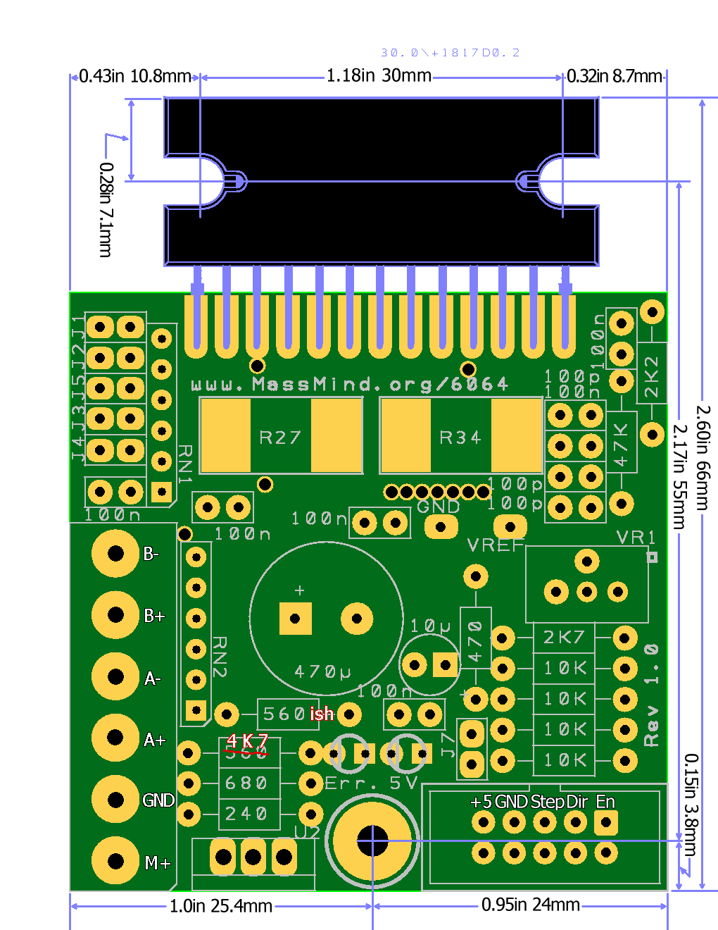 |
| PMinMO connector:
|
| Kit |
Part |
Qty |
Description |
|
|
|||
| PCB | 1 | The printed circuit board only. Double sided, plated thru holes, professionally made. | |
|
|
|||
| U1 | 1 | THB6460AH aka TB6564 Bipolar 4.5A, 48V Datasheet (pdf) | |
|
Including the Chip and PCB listed above |
|||
| R27,34 | 2 | 0.2 Ohm SMD 2W WSR2 (critical) | |
| VR1 | 1 | Potentiometer 5K Trim | |
| C1-3 | 3 | 100p 5V | |
| C4-8,11 | 6 | 100n 50V | |
| C9 | 1 | Electrolytic 10µ 16V | |
| C14 | 1 | Electrolytic 470-560µ 63V Low ESR High ripple | |
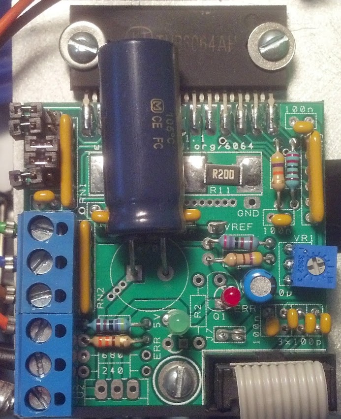
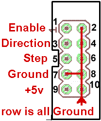
| CONN1 | 1 | 0.1" 2x5 Shrouded PMinMO w/Step, Dir, En and +5volt power | |
| J1-5 | 1 | Header 0.1" 2 x 5 | |
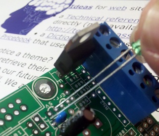
| J6 | 3 | 0.2" Terminal Block | |
| J7 | 1 | Header 0.1" 2x1 shorted to provide +5 volts from PMinMO connection. | |
| RN1-2 | 2 | 10K SIP-6 | |
RN3 |
1 |
10K Ohm ¼W. R1-3 and R5 are replaced with a single network resistor RN3 in Rev 1.1 | |
| R4 | 1 | 2K7 Ohm ¼W | |
| R10 | 1 | 47K Ohm ¼W | |
| R12 | 1 | 470 Ohm ¼W | |
| R13 | 1 | 2K2 Ohm ¼W | |
R1 |
1 | 330-2K2 Ohm ¼W Power LED current limit. On Rev 1.1, this resistor is labeled R1 vice R21 | |
R7 |
1 | 4K7 Ohm ¼W Error LED current limit, LED will be very dim, but a
lower resistor will blow the output. On Rev 1.1, this resistor is labeled R7 vice R36 |
|
| LED1 | 1 | Red LED 3mm | |
| LED2 | 1 | Green LED 3mm | |
|
Not Supplied: |
|||
| R2 | 1 | On Rev 1.1 PCB, R2 is not needed for the standard error LED which is installed at Q1, not below the 5V power LED. | |
 On the original and rev 1.1 of the PCB, you can provide the +5 logic power from the motor power supply by adding a voltage regulator. This will not fry the THB6064AH they way it will fry the TB6560, because it protects against latch up on start. Here is a video on the assembly. |
|||
| R"240" | 1 | 330 Ohm ¼W (install at "240") | |
| R"680" | 1 | 1K Ohm ¼W (install at "680") | |
| U2 | 1 | LM317 Voltage Regulator | |
|
Amplified Error Reporting For Rev 1.1 PCB's: Note that this option is not supplied with the kit, and is a non-standard , use of the PMinMO connector to feed back an error condition to the PC or other motion controller. The error pin from the THB6064AH has very limited drive strength. To safely drive an input back to a PC, it needs some amplification. For this option, R7 should be 10K, and a standard switching transistor (e.g. BC557) installed as Q1 to provide an amplified error signal. In this case, R2 can be a ~560 Ohm resistor which will not only drive an error LED installed on the side of R2 near the mounting bolt, but which can also be routed to pin 7 of the PMinMO header by cutting the trace which connects pin 7 to the ground pin 8, and then wiring pin 7 to R2. |
|||
| Q1 | 1 | BC557 | |
| R7 | 1 | 10 K Ohm | |
| R2 | 1 | ~560 Ohm | |
Terminal Block Control Signals
The Version 1.2 PCB adds two extra holes on the
PMinMO connector at lower right so that terminal
blocks can (optionally) be used instead of a 2x5 header. In that case, note
that the terminals don't carry logic power. And so either the 5 volt power
regulator must be installed, or a 2 pin header installed between the right
pad of J7 and the GND pad just above it and logic power supplied there.
 1. Long lead / Pin 1 in the square hole.
Pin one or the positive lead is always marked on our PCBs with a square hole.
On components where pin one isn't marked on the component package, the longer
lead is always positive, and we make that pad square on the PCB.
1. Long lead / Pin 1 in the square hole.
Pin one or the positive lead is always marked on our PCBs with a square hole.
On components where pin one isn't marked on the component package, the longer
lead is always positive, and we make that pad square on the PCB.
2. Don't solder the component in right next to the PCB; leave a little bit (1/4 inch, 1 mm) of lead.
a. This helps prevent the component from overheating when you solder, and during operation. It also gives you some lead to cut if you need to repair the board or if you get the component in the wrong hole. Trying to desolder the leads without cutting them is much more likely to damage the PCB.
b. To keep the components off the PCB, insert the leads so that the component is about a quarter inch up, then bend the leads together at that point, crossing them over each other at about 45 degrees. You could also bend them out, but then they would be in the way of the soldering iron, which is almost always coming in from the outer edge of the board. When you turn the PCB over to solder on the back side, the component will fall down to the point where the lead is bent, providing the correct spacing on the component side.
c. Solder one lead, stop and check the positioning and that it is the right component in the right place the right way around... then solder the other lead.
3. Work from the inside toward the edge, low components to high components. It's best to solder down any SMT components first, since they are certainly the lowest, then work up and out. Solder a few through hole components in a line if you can, then clip leads and do the next line.
4. It's important to clip all leads as short as possible to prevent shorts to the heatsink.
Keep the leads... they become the jumper for the power source and can be used for the test points.
5. Good soldering is adequite heat to both pin and pad for a few seconds
at a time, repeated until the solder flows completely. Keep your iron
hot, clean, and tinned. Make solid contact with both pin and pad, but never
stay on more than a few seconds. The count of 5 should be enough. If the
solder didn't flow around all of the pin and pad in that time, get off, let
it cool, and try again. See our soldering class:
http://goo.gl/HuCC1R MassMind Soldering
201
 Passive Components
1. [ ] Surface mount Resistors. There are only two surface mount devices on this board, unless you count the driver chip as SMT because of the way it's being mounted. The components are large compared to most SMD and they really are easy to solder. The only trick is that there are no holes to hold the components in place by the leads, so you need some way to keep them in place while you solder. Almost anything that has 3 or 4 corners and won't melt can be used. A metal box, a heat sink, an aluminum extrusion, … anything. Probably the best is made from vice grips and a screw driver tip. If you don't have vice grips, wrap a rubber band around the far end of the handle of a pair of pliers. Or just tape one side of the part down with clear tape!
Once the part is held down in position, touch the pad, next to the end of the part, solder, flow, off. Solder one side of each part, check position, solder the other side.
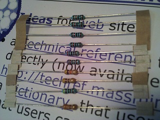 2. [ ]
Resistors: There are several
different values of resistors and a lot of the values look alike. Take care
and be sure you have it right before you proceed. For example, there are
47K, 4K7, and 470. And there is a mix of 4 and 5 band resistors (low and
high precision). Getting them right is harder than you think, certainly harder
than soldering surface mount components. An amazing percentage of people
are, at least partially, color blind. Some don't know it until they start
trying to sort out resistors. And even if you aren't, it takes a strong light
and good luck to tell orange from gold or brown from purple on some of these
packages.
2. [ ]
Resistors: There are several
different values of resistors and a lot of the values look alike. Take care
and be sure you have it right before you proceed. For example, there are
47K, 4K7, and 470. And there is a mix of 4 and 5 band resistors (low and
high precision). Getting them right is harder than you think, certainly harder
than soldering surface mount components. An amazing percentage of people
are, at least partially, color blind. Some don't know it until they start
trying to sort out resistors. And even if you aren't, it takes a strong light
and good luck to tell orange from gold or brown from purple on some of these
packages.
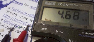 We strongly recommend using a multimeter
to check the values of the resistors rather than reading the color codes.
When using a meter to read resistance, be sure not to let your fingers touch
both leads. In other words, one test lead should be held to the resistor
lead by a clip, or by pressing it against a surface and NOT by holding the
two together with your fingers. Otherwise, the reading can be off due to
the lower resistance path offered by your skin.
We strongly recommend using a multimeter
to check the values of the resistors rather than reading the color codes.
When using a meter to read resistance, be sure not to let your fingers touch
both leads. In other words, one test lead should be held to the resistor
lead by a clip, or by pressing it against a surface and NOT by holding the
two together with your fingers. Otherwise, the reading can be off due to
the lower resistance path offered by your skin.
If you must read the bands, start by arranging them with the colorful bands to the left. In most cases, that will give you the correct order, with the tolerance band on the right and the actual value reading from left to right. There are exceptions. The 5 band 10K resistors currently supplied with the kit are brown, black, black, red, brown (1, 0, 0, two more zeros, and a 1% tolerance). Read it each way, figure out which one makes more sense given the resistors in the set... and then check it with your meter. Really... For less than $25 you can get a half way decent digital multimeter (watch out, it doesn't include the special battery) from your local Radio Shack right now or order one from eBay china and wait a month for it to show up. Believe it or not, WalMart (gag) sells a pretty good one in most of their stores: The "Equus 3320 Innova" for about $20.
The PCB is marked with the values rather than the component name to eliminate another possible source of error in transcribing the part (R1) to the value (10K) to the actual physical component (brown, black, black, red, brown OR brown black orange gold). There wasn't room to put the colors on the PCB. Now you just go from value to component... Mostly; a couple of the resistors are marked Rsomething because the value supplied could change. R1 (aka R21) may actually be anything from 330 up to 1K. This is not a critical value component. Populate the other resistors first, and whatever is left over, should be a value in that range.
Errata:
On the Rev 1.1 and up PCB, the "ERROR LED" resistor (originally
R36) is labeled R7 on the new board and is the 4K7 resistor. The red LED
should be installed to the right of R2 above J7 with the long lead in the
square hole marked Q1 and the short lead up and to the right in the round
hole nearest the "E" in ERR. R2 is not used. This provides a simple error
indicator via the LED and no amplification of the error signal.
On the Rev. 1.0 PCB, the resistor supplied for R21, to pin
1 of RN2, which is marked on the PCB as being 560, may actually be anything
from 330 up to 1K. This is not a critical value component. Populate the other
resistors first, and whatever is left over, should be a value in that range,
and should be installed for the 560 or R1. Also, the value for R36 (next
to the Err LED) is incorrectly printed as 560 when that resistor must be
a 4K7. Place the supplied 4K7 resistor in the position marked "560".
3. [ ] Variable Resistor: This is the drive current adjustment. It can be installed either way but being able to get in there to turn it is the trick. Make sure you will be able to get to it after installing the other components. On PCB Rev 1.1, it's probably best to install it facing the edge of the board. If you install it facing the capacitors, and you leave about ¼” of lead between each capacitor and the PCB, you can bend them over out of the way after they are soldered down and so clear a path to adjust the current. Take care not to melt the case by letting each lead cool a bit after soldering.
If you like, you can even bend the leads on the variable resistor and install it flat agasint the PCB, with the shaft up. It will just hang a bit over the edge that way
4. [ ] Network Resistors: It's all about the dot. Network resistors all have a (very tiny, dimly printed, very hard to see) dot at one end, usually down next to the pin. That pin is pin 1 and pin 1 goes in the square hole. Bend the outermost pins out so it won't fall down when you turn it over to solder it. Then push the pins back down so they are just through the hole so you leave a little lead on the component side. Solder one pin, check positioning, and solder the rest.
5. [ ] Capacitors: The little capacitors will be marked with a number: 101 or 104 which represents the first two digits and the number of zeros in pico Farads. 101 is 100pF. 104 is 100000pF or 100nF or 0.1uF. So the ones marked 100n on the PCB get the 104's and the 100p's get 101s. On the Rev 1.1 PCB, all the caps are clearly labeled and do not get in the way of the current adjust pot.
Errata: Rev 1.0 PCB only, watch out for the block of caps between VR1 (the current adjust potentiometer) and the top of the board; the top cap is 100p, not 100n. The 100n is the second one down. The next two are 100p. Note: Be sure to install those caps next to the current adjust potentiometer in such a way that you can bend them down clear of the screwdriver so you can make that adjustment.
The medium and large electrolytic caps go in with the long lead in the square hole, and the stripe side towards the round hole. And the really big one is an exception to the "leave some leads" rule. It can be installed all the way down on the PCB for physical stability. And it's probably best to set it aside and come back to it after you have done all the other components.
6. [ ]
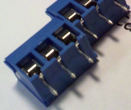 Terminal Blocks: Slide the two sets of
terminal blocks together so that the rail and groove interlock.
Terminal Blocks: Slide the two sets of
terminal blocks together so that the rail and groove interlock.
7. [ ] Unless you are installing the onboard logic power regulator option, use one of the clipped resistor or other component leads to short J7 so you can get logic power via the PMinMO header. The PMinMO header can be connected to the 4Axis board, or directly to a PC parallel port cable. You can provide power on that PMinMO header, pin 9 from the 4 Axis board, a USB port, or your own 5+ regulated power source. If you keep that J7 jumper wire up off the board a little, it makes a great test point for logic power.
[ ] If you do install the onboard logic power regulator option, the LM317 goes in U2, with the tab towards the outside of the PCB, and the 240 and 680 ohm resistors are just above it. Note: you may be supplied with a 330 ohm resistor (that goes in place of the 240) and a 1K (instead of 680); 330/1000 is actually closer to 5V. Keep in mind, you will be applying >9 volts to VM+ when testing logic power below.
8. [ ] Test Points: Form loops from a couple clipped leads and push both ends into the hole for the VREF test point and the GND test point.
9. [ ] Jumpers: When you solder on the 2x5 header for the options jumpers and the shrouded 2x5 PMinMO header, it's a good idea to bounce around in the pin order rather than just going down the line. It keeps the plastic from getting soft and perhaps not holding the pins straight. Note the notch in the shrouded header is towards the resistors. On the Rev 1.1 board, the order of the option jumpers has been re-arranged in numerical order.
10. [ ] LEDs: The long lead goes in the square hole, leave a little lead so the LEDs are up off the PCB and where you can see them. On the Rev 1.1 PCB, with a standard build, the Red "ERR" LED should be installed above J7 and right of R2 (long pin in the square hole as always) and NOT under the 5V indicator LED. If you want to feed back the error signal to your controller see the "Rev 1.1 Option 2 "AMPLIFIED ERROR FEEDBACK" text above. This is not recommended.
Dont' forget the big Capacitor if you left it for the end. Assembly time to this point is about 30 minutes.
11. [ ] At this point, without the chip installed, do a visual inspection,
preferably with a magnifying glass. If you want to be extra careful, you
can check the resistances to ground at the pads where the main chip will
be soldered on. Note: This table assume no option jumpers are in place.
If they are, the DCY# and M# pins will be <0.2 instead of 12K
TOP:
Pin	Signal	Pad*	Normal
1square	ALERT	1	OO
3 	DCY1	2	~12K or <0.5
5 	VREF	3	470-5K5
7 	M1	4	~12K or <0.5
9 	M3	5	~12K or <0.5
11	NFB	6	<0.5
13	PGNDB	7	<0.2
15	NFA	8	<0.5
17	PGNDA	9	<0.2
19	RESET	10	~12K
21	STEP	11	~12K
23	OSC2	12	47K
25	DOWN	13	7K6
VREF = ~470 to ~4K as the trim pot is turned |
BOTTOM:
Pin	Signal	Pad*	Normal
2GND	SGND	1	<0.2
4 	DCY2	2	~12K or <0.5
6 	VMB	3	~3M5
8 	M2	4	~12K or <0.5
10	Out2B	5	10K
12	Out1B	6	10K
14	Out2A	7	10K
16	Out1A	8	10K
18	EN	9	~12K
20	VMA	10	~3M5
22	DIR	11	~12K
24	VDD	12	>7K
|
Then apply 5V logic power at pin 9 of the PMinMO header. Now the 5V logic power system can be checked, the +5v led should be on and the Vref can be measured and adjusted to a low value: 0.4-0.5V. Power off and prepare for finally assembly.
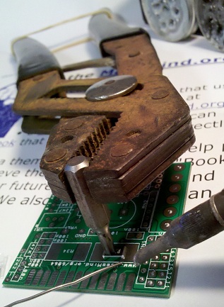
12. [ ] The big THB6064AH chip: Since this product has a MOS structure, it is sensitive to electrostatic discharge. These ICs are highly sensitive to electrostatic discharge. When handling them, please be careful of electrostatic discharge, temperature and humidity conditions. Wear a grounding strap when touching the chip and work on an anti-static surface.
The IC fin is electrically connected to the rear of the chip. If current flows to the fin, the IC will malfunction. If there is any possibility of a voltage being generated between the IC GND and the fin, either ground the fin or insulate it. We recommend that you directly connect the IC to the heatsink, and ground the heatsink.
If consistent mounting hole locations are important to you, use a drilled heatsink or template plate for this last step. Drill and tap for M3 or #4-40
Mount the chip and PCB using 3 #4-40 or M3 screws. Temporarily mount the chip to the heatsink first. On a large heatsink, you should also mount the PCB with a spacer to raise it up a bit so it won't short out underneath. Spacer height can be about 0.1 inch or 3mm. You can use an M3 or #4-40 nut, a stack of washers, or cut off a bit of tubing like an old bic pen barrel. If the heatsink is smaller than the PCB, like our little CPU coolers, just mount the chip in the center of the heatsink and secure the PCB to the cabinet next to the heatsink.
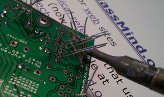
Slide the PCB between the chip's pins, align it carefully, and screw it down. The wide point on the outer pins should be just at the edge of the PCB. Any farther in, and the pins will start to spread apart and not lie flat on the pads. Make sure all the pins are flat on the pads so the solder will flow nicely over the length of the pin and form a strong connection. Bend them carefully if needed. Solder one pin by placing the tip of the iron on the pad near the pin and let the solder flow around and under the pad. Check placement, alignment, and orientation and then solder down the rest of the pins. It's a good idea to bounce around and pause once in awhile to keep the heat from building up in the chip.
Now take the chip and the PCB off the heatsink, turn them over and solder the pins on the back side. Check the following resistances from the actual pin of the chip (not the PCB pad) and these test points:
Finally, reassemble with a bit of heatsink paste under the chip. That paste makes a huge difference in high temperature operation.
Version 1.0 |
 Version 1.1 |
13. [ ] Apply only the +5 volt power again, verify the power LED lights and nothing gets hot.
14. [ ] Power off, connect motor power (but don't turn it on!) and the motor. For help with sorting out the motor leads, see: Stepper Motor wiring
DECAY J J Mode |
MODE |
15. [ ] Set decay and mode by adding or removing jumpers. You might start with only 2 and 3 jumpered: 40% decay and 16th microstepping.
16. [ ] Verify the current control potentiometer is set all the way to the lowest setting. Apply logic power first, then motor power. The motor should lock, but not turn. Make sure the drive chip and motor are not heating. Carefully adjust the current setting to 30% of the motors rated capacity. Why only 30%? Because when the motor is not turning, the driver is in idle and as soon as it gets a step pulse, it's going to increase the drive power automatically. Please do NOT measure the current via the +VM or positive motor supply lead: Because this is a chopper driver, the current measured at the +VM line is much lower than the actual motor; as much as a quarter to a fifth the actual current; to set current limit, you must measure VRef voltage.
To calculate the correct VRef voltage (at speed): Io = Vref * 1/3 *
1/Rs
Since Rs = 0.20 Ohms then Io = Vref * 1.667 (at speed)
For example, when Vref = 2.4 volts, Io = 4 amps (max) and when
Vref = 0.5 volts, Io = < 1 amp (minimum).
When at rest, the actual Vref for Io = 4 amps (max) will be 30% of 2.4 volts or 0.72 volts. So to set for maximum amperage, while the motors are at rest, adjust Vref to 0.72 volts. For Io = 1 amps (min), when at rest, Vref should be adjusted to 30% of 0.5 volts or 0.15 volts.
Start with the current you want in amps. Divide that by 1.667 to get the correct voltage for Vref when running. Then divide that by 3.333 to get the correct voltage for Vref when resting. Set Vref to that voltage when powered but resting (not stepping), by following these steps:
NORMAL VOLTAGES WITH MOTOR AND LOGIC / MOTOR POWER
Pin	Signal	Normal
24	VDD	5V (4.6 to 5.5)
6 / 20	VMB/VMA	12V to 50V
5	VREF 	0.2V to 2.4V
23	OSC	1.2V
19 	RESET	4.6V
 17. [ ] Now connect the step and direction signals
and spin the motor. These should be < 0.8V when low and > 2.0V when
high. The Vref reading should increase to your desired amperage setting divided
by 1.667 while the motor is in motion, and drop back down when you stop
it. Let it work for at least 10 minutes to verify that nothing is
overheating.
17. [ ] Now connect the step and direction signals
and spin the motor. These should be < 0.8V when low and > 2.0V when
high. The Vref reading should increase to your desired amperage setting divided
by 1.667 while the motor is in motion, and drop back down when you stop
it. Let it work for at least 10 minutes to verify that nothing is
overheating.
Note: If you are building the RAMPs adapter cable, please do NOT bridge the two pads on the bottom of the adapter PCB. Bridging these pads with solder will cause the enable signal from the RAMPs board to be fed into the driver. However, the polarity of that signal for our driver is the opposite of that for the standard Pololu boards. As a result, the motors will lock when not moving, and release, failing to move, when the RAMPs system tries to move them. The enable signal is not required on the THB6064AH driver because it is enabled by default, and automatically goes into a low power hold when not in motion. If you do wish to make use of the enable line, you will need to change the polarity in the firmware. E.g. For Marlin, change the X, Y, Z or E _ENABLE_ON from 0 to 1 in the Configuration.h file
See also:
Questions:
Hello!
I need to connect the motor Nema34 to Ramps 1.4.
Network recommend to use your project.
Today I need 2 driver.
I need driver in assembled condition. Still need adapters cable Pololu.
Tell me, is it enough to work, or will need something. I am ready to pay today. What are the dates of dispatch and delivery to Russia?
Regards, Vlad
James Newton of MassMind replies: Hi Vlad, as per our email conversations, you would be much better off using a Gecko Drive and making a custom cable.+
I'm building a 24x30" wood router. It will have plastic linear bearings (8020 style), 5 start 10tpi acme screws. Motor torque requirements come out below 100 oz-in for several methods, including the one here. Why do people use 300 oz-in motors on machines this size? I realize torque drops with speed.
I like the looks of your 4A driver.
Steve
James Newton of MassMind replies: Because pull out (or detent) torque and hold in (holding) torque are different. If you need something held at 100 oz-in, then a 100 oz-in motor is fine. If you need something to turn at 100 oz-in, then you probably need at least a 300 oz-in motor. See: Torque for more+
James, i was looking at the BoB and I see you do not use optocoupler input/outputs which seems normal on others I have looked at, is there a reason for this?
James Newton of MassMind replies: It's a risk / cost assesment. In all the years I've been doing this, I've seen exactly ONE case of a driver apparently taking out it's controller. And that was on Andreys massive cement 3D house printer when he was pushing the drivers past spec. On the other hand, search CNCZone for problems caused by optocouplers. IMHO, it just isn't worth it. Especially since older PC's with parallel ports are now so inexpensive. If you want a version with opto's contact the mfgr Luc.+
I am waiting on receiving your 3 axis kit,
I will be using it with Linuxcnc, do you have recommendations for step & hold timings etc.
Reading the datasheet is not very clear on what to set them to
James Newton of MassMind replies: Minimum 2.3uS step and your guess is as good as mine on the direction line; it's not specified in the datasheet at all. I haven't seen any issues with reasonable times of a few uS.+
Why is that 4 10k resistor pulling the motors output to ground, not better a diode or nothing connected? Why those 10k and 100nf parts in the reset pin, why not link to +5V if the device claims to be safer than TB6065? Thank you!
James Newton of MassMind replies: The diodes are built in, the resistors reduce the size of the diodes required. The parts on the reset pin keep the driver from running until after the supply voltages have stabilized (some spikes on power up are pretty common in high power supplies).+
good day, your 6064 Stepper Motor Driver / breakout / cables 3 AXIS FULL KIT! $ 120.90 is already assembled and welded? already has the sink as in the picture?
there is already an adapter cable for ramps 1.4?
James Newton of MassMind replies: No. It is a kit. You must solder it together.+
Hi james, forgive my ignorant question of electronic, but is it possible, with ramps 1.4 and marlin, move 3 axis, and then 3 stepper motors of my 3d printer, with the kit "3 AXIS FULL KIT"? ?If no, what else (or less) I need? Thank you in advance.
Alessandro
James Newton of MassMind replies: No worries! The RAMPS board would replace the 4Axis board in that kit, so you only need 3 of the THB6064 driver kits, and you will need to make a cable to connect the RAMPS board to the drivers. I'll be happy to help you make the cable, showing which wires need to connect where. In the future, we hope to provide a ready made cable, but that is not available yet.+
jtrantow says (speaking about his experience with a cheap THB6064AH knock off from China that would only turn one direction if at all) "Notice massmind design uses a 10k pullup in conjunction with the TB6564AH internal pulldown so it won't have this problem. This is an easy fix if you don't mind working with the three surface mount resistors, but I wish I had been aware of the massmind kit. It would have been quicker to build up the kit than debug and repair this board." +
Comments:
| file: /Techref/io/stepper/THB6064/old.htm, 54KB, , updated: 2018/8/8 14:23, local time: 2025/9/13 06:55,
216.73.216.127,10-2-23-136:LOG IN
|
| ©2025 These pages are served without commercial sponsorship. (No popup ads, etc...).Bandwidth abuse increases hosting cost forcing sponsorship or shutdown. This server aggressively defends against automated copying for any reason including offline viewing, duplication, etc... Please respect this requirement and DO NOT RIP THIS SITE. Questions? <A HREF="http://techref.massmind.org/Techref/io/stepper/THB6064/old.htm"> THB6064 MassMind Stepper Motor Driver Kit</A> |
| Did you find what you needed? |
Welcome to massmind.org! |
Welcome to techref.massmind.org! |
.