|
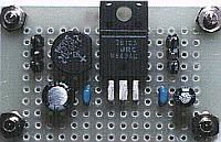
The voltage regulator for the dancing lights controller |
 This is the IC to make the stabilized voltage of +12 V. The a maximum of 1-A output current can be passed. This type of regulator is sometimes called the series regulator or the linear regulator. The electric current with the quantity which is the same as the output current approximately flows through the input. Because it passes only the about 100-mA electric current this time, I don't put the heat sink.  This diode bridge is used to rectify the voltage of the alternating current in the full wave. I used the one of the maximum reverse voltage of 200 V, the forward direction maximum electric currents of 1.5 A. 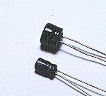 The 3 terminal regulator has the function to reduce the ripple. However, I put the ripple filter capacitors to the input and output of the 3 terminal regulator. Because the voltage on the side of the input becomes more than 20 V, the capacitor with the high work voltage must be used for the capacitor on the side of the input. I used 50WV. 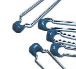 The regulator sometimes oscillates. I put these capacitors for the removal of the high frequency noise and the oscillation prevention. I used multilayer ceramic capacitors. 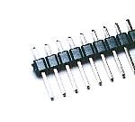 These are used to connect the wire with the circuit outside. When connecting the wiring with the printed board directly, there are not necessary. 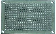 I cut and used the universal board with the 15 x 25 holes. The universal board 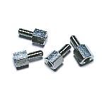 I used these studs to install the printed board to the case. |