The best way to explain a logic gate is to watch one working. If Java and
LogicSim are working, in the box below you will see some red switches
(![]() ), lights
(
), lights
(![]() ), and little boxes hooked up
with lines. If you don't see those, look for a warning message asking you
if you want to allow LogicSim and Java to run. Please allow them. If that
doesn't work, you can check if you have Java at
java.com (look for the "Do
I have Java?" link) and you can install it if you don't. For Google Chrome, see the CheerpJ Applet Runner
), and little boxes hooked up
with lines. If you don't see those, look for a warning message asking you
if you want to allow LogicSim and Java to run. Please allow them. If that
doesn't work, you can check if you have Java at
java.com (look for the "Do
I have Java?" link) and you can install it if you don't. For Google Chrome, see the CheerpJ Applet Runner
If you can't see the simulation below, try this HTML version of the Falstad simulator: NAND Gate or NAND Circuit.
Click on the first (#1) switch (you may need to click twice) and see how it turns on and off. Click a few times. See the line from the switch to the light? It is also red or black. And the light is turning on and off. There is also a "0" or "1" by the switch and light.
We have a lot of ways to say the same thing: OFF is "0" or black. ON is "1" or red. We can even say OFF is "LOW" or "NO" and ON is "HIGH" or "YES".
Now move down to the #2 and #3 switches. They go into a box. If the first
box looks like this:
![]()
and if you are in the US, then please click the "Settings" menu and
then "gate design" and then "us" so that it looks like this
![]()
instead. Both are good, but the US one is what you will see in most books.
Click the #2 switch on, but let #3 stay off. See the red line from #2 to the box? But the line from the box to the light is still off. This box has an AND gate. It only turns on when BOTH the top AND bottom inputs are on. Turn on #3. Now the light is on. Turn OFF #2 and see that the light goes off. Both #2 AND #3 must be on before the light will turn on.
Now look at switch #4. It goes to a NOT gate. The light is already on, but if you push the switch ON it will go OFF! The NOT gate reverses things. On -> off and off->on.
Switches #5 and #6 go to a NAND gate. This is the gate that every computer is made from! It is made from an AND gate with a NOT gate stuck on. It will only go off when both of its inputs are on. Try it and see.
The NAND gate gets its name from it's parts: NOT + AND = NAND. It is just easier to say "NAND" than to say "NOT AND"
|
icon for a NAND gate. Note the shape for the AND gate and the little circle from the NOT gate. If the little circle was not there, it would be an AND gate. |
Remember: The NAND gate is NOT off until both the top AND bottom inputs are on.
NAND gates are hard to turn off. You have to turn both inputs on before the output will go off.
1. Turn all the lights off. Off = 0
2. Turn all the lights on. On = 1
3. Turn the top and third lights on and the second and forth lights off. You should see 1, 0, 1, 0 from top to bottom.
4. Make the lights show the pattern 0, 1, 0, 1 from top to bottom.
So what? A single NAND gate can't do much. But wait till you see what we can do with two of them. Get ready to meet the RS Flip Flop, also known as the BIT. Or if you like you can find out more about the NAND: NAND gates can make NOT, AND, OR, NOR and other things... and XOR and XNOR gates, which detect if things are different or equal.
See also:
Click the word "simulate" at the top of LogicSim so that it is in a grey box not a blue box. Now use the right mouse button to click on the #5 switch and left click on properties in the little pop up menu. Change the Switch-Type to Click-Button then click Use. Do the same thing for #6. Click simulate back on to it's blue box. Now push both #5 and #6 to turn on the light. What? I can do it... ;^)
There are lots of ways to make things that work like NAND gates:
You can use Transistors: (this is how NAND gates are made in computers)
Paper goats ^ (check the video^)

DNA and bacteria ^
Dominos ^
or even diodes and relays:
NASA can make them from Silicon Carbide
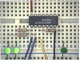
and you can buy NAND gates in sets of four from just about anywhere for 50
cents:
http://www.findchips.com/avail?part=74LS00
and build circuits with them on a white board
More:
| file: /Techref/logic/nand.htm, 10KB, , updated: 2021/2/2 10:52, local time: 2025/10/27 14:43,
216.73.216.180,10-8-63-169:LOG IN
|
| ©2025 These pages are served without commercial sponsorship. (No popup ads, etc...).Bandwidth abuse increases hosting cost forcing sponsorship or shutdown. This server aggressively defends against automated copying for any reason including offline viewing, duplication, etc... Please respect this requirement and DO NOT RIP THIS SITE. Questions? <A HREF="http://techref.massmind.org/techref/logic/nand.htm"> Digital Logic Tutorial, NAND</A> |
| Did you find what you needed? |
Welcome to massmind.org! |
Welcome to techref.massmind.org! |
.