Circuit explanation
for the ultrasonic detection unit(1)
|
The transmitter circuit, the receiver circuit of the ultrasonic are the circuit which is the same as the ultrasonic range meter.
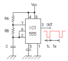 IC1 is the oscillation circuit to control the sending-out time of the ultrasonic pulse. The circuit is the same as the ultrasonic range meter but the value of the resistors and the capacitors are changed. The oscillation frequency is the same. The time of the oscillation pulse can be calculated by the following formula. Actually, with the error of the parts, it is different from the calculation a little. The condition : RA = 1M-ohm, RB = 15K-ohm, C = 0.1µF
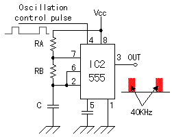 IC2 is the circuit to make oscillate the ultrasonic frequency of 40KHz. IC2 is the circuit to make oscillate the ultrasonic frequency of 40KHz.Oscillation's operation is same as IC1 and makes oscillate at the frequency of about 40 KHz. It makes RB>RA to bring the duty(Ratio of ON/OFF) of the oscillation wave close to 50%. The frequency of the ultrasonic must be adjusted to the resonant frequency of the ultrasonic sensor. Therefore, I am made to be able to adjust the oscillation frequency by making the RB the variable resistor (VR1). The output of IC1 is connected with the reset terminal of IC2 through the inverter. When the reset terminal is the H level, IC2 works in the oscillation. The ultrasonic of 40KHz is sent out for the 1 millisecond and pauses for the 68 milliseconds. The calculation example of the frequency is shown below.
The condition : RA = 1.5K-ohm, RB = 15K-ohm. C = 1000pF
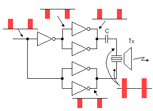 The inverter is used for the drive of the ultrasonic sensor. The two inverters are connected in parallel because of the transmission electric power increase. The phase with the voltage to apply to the positive terminal and the negative terminal of the sensor has been 180 degrees shifted. Because it is cutting the direct current with the capacitor, about twice of voltage of the inverter output are appied to the sensor. 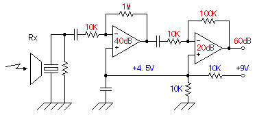 The ultrasonic signal which was received with the reception sensor is amplified by 1000 times(60dB) of voltage with the operational amplifier with two stages. It is 100 times at the first stage (40dB) and 10 times (20dB) at the next stage. The ultrasonic signal which was received with the reception sensor is amplified by 1000 times(60dB) of voltage with the operational amplifier with two stages. It is 100 times at the first stage (40dB) and 10 times (20dB) at the next stage.As for the dB (decibel), refer to "Logarithm Table". Generally, the positive and the negative power supply are used for the operational amplifier. The circuit this time works with the single power supply of +9 V. Therefore, for the positive input of the operational amplifiers, the half of the power supply voltage is appied as the bias voltage and it is made 4.5 V in the central voltage of the amplified alternating current signal. When using the operational amplifier with the negative feedback, the voltage of the positive input terminal and the voltage of the negative input terminal become equal approximately. So, by this bias voltage, the side of the positive and the side of the negative of the alternating current signal can be equally amplified. When not using this bias voltage, the distortion causes the alternating current signal. When the alternating current signal is amplified, this way is used when working the operational amplifier for the 2 power supply with the single power supply. As for the operation of the operational amplifier, refer to "Operation explanation of the triangular wave oscillator". 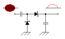 The detection is done to detect the received ultrasonic signal. It is the half-wave rectification circuit which used the Shottky barrier diodes. The DC voltage according to the level of the detection signal is gotten by the capacitor behind the diode. the Shottky barrier diodes are used because the high frequency characteristic is good. As for the Shottky barrier diode, refer to "Diodes". 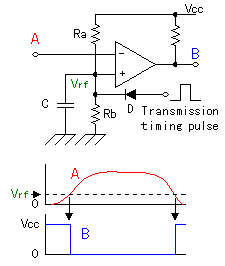 This circuit is the circuit which detects the ultrasonic which returned from the object. The output of the detection circuit is detected using the comparator. At the circuit this time, the operational amplifier of the single power supply is used instead of the comparator. The operational amplifier amplifies and outputs the difference between the positive input and the negative input. In case of the operational amplifier which doesn't have the negative feedback, at a little input voltage, the output becomes the saturation state. Generally, the operational amplifier has tens of thousands of times of mu factors. So, when the positive input becomes higher a little than the negative input, the difference is tens of thousands of times amplified and the output becomes the same as the power supply almost.(It is the saturation state) Oppositely, when the positive input becomes lower a little than the negative input, the difference is tens of thousands of times amplified and the output becomes 0 V almost.(It is in the OFF condition) This operation is the same as the operation of the comparator. However, because the inner circuit is different about the comparator and the operational amplifier, the comparator can not be used as the operational amplifier. At the circuit this time, it connects the output of the detection circuit with the negative input of the signal detector and it makes the voltage of the positive input constant.
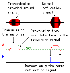 There is another device in this circuit. It is the diode (D) which connects with the side of the positive input. There is another device in this circuit. It is the diode (D) which connects with the side of the positive input.The pulse sending-out timing signal of the transmitter is appied to this diode. So, it makes not detect the transmission signal which was crowded when sending out the ultrasonic signal from the transmitter and going around to the reception sensor, making the voltage of the positive input of the signal detector rise in the pulse sending-out timing signal. The transmission signal has the remaining signal even if it stops the transmission timing pulse. So, it makes the falling of the transmission timing pulse gentle with the capacitor (C) and it is preventing from the mis-detection by the remaining signal. The value of this capacitor is the one point which decides the efficiency of the equipment. The detection start time becomes late when the value of this capacitor is big and can not do the short distance. The equipment this time makes the transmission pulse long(About 1 millisecond) to make detect possible to the about 10-m distance and makes the capacitor of the detector big a little. Therefore, the shortest distance becomes about 40 cm. To detect the short distance, making TL in IC1 short, the value of the capacitor of the signal detector must be made small. Way, in the time that the ultrasonic goes and returns in the 30-cm distance at 20°C, it is the 1.75 milliseconds. 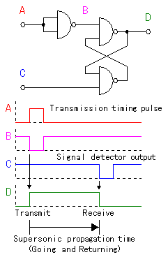 This circuit is the gate circuit to measure the time which is reflected with the object and returns after sending out the ultrasonic. It is using the SR (the set and the reset) flip-flop. For the details of SR-FF, refer to "The operation explanation of the D-type flip-flop". The set condition is the time which begins to let out the ultrasonic with the transmitter. It uses the transmission timing pulse. The reset condition is the time which detected the signal with the signal detector of the receiver circuit. That is, the time that the output of SR-FF (D) is in the ON condition becomes the time which returns after letting out the ultrasonic. 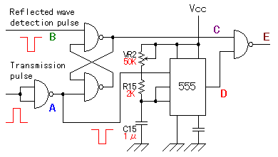 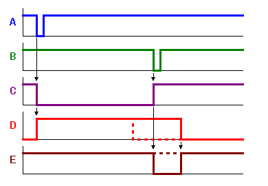 This circuit is the circuit to judge whether or not the reaching time of the reception signal is shorter or longer than the setup time. It sets the time using the 555 timer circuit. The transmission timing pulse is used for the trigger of the timer. The 555 timers begin the operation when the input trigger becomes the L level. So, it is inputting the transmission timing pulse through the inverter(It uses the 2 input NAND). The alarm output(E) becomes the L level if the output of the timer(D) becomes the H level and the output of the measurement gate circuit(C) becomes the H level. When the timer does in the time-out, the output of the timer(D) becomes the L level. So, after that, even if the output of the measurement gate circuit(C) becomes the H level, the alarm output (E) is as the H level. If the D point becomes the H level before the C point becomes the L level, the wrong pulse with the alarm output (the E point) is output. In the actual operation, because that the C point becomes the L level is earlier than the operation beginning of the timer, I don't put the delay circuit. It made the range of the alarm from about 40 cm to 10 m. The most short distance is limited by the transmission pulse mis-detection prevention circuit. The most long distance is limited by the transmission level of the ultrasonic, receiver sensitivity and then the interval of the transmission of the transmission pulse.
In the time to be propagated by 80 cm (the going and returning), it is as follows.
It is possible to calculate as follows in the minimum time and the maximum time.
That is, it becomes R = T/1.1 C. At the circuit this time, 1µF of the capacitor is used.
At the actual circuit, 2K-ohm is used.
As the value of the variable resistor, it becomes the value which deducted RS from RL. At the circuit this time, 50K-ohm is used. 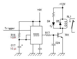 The output of the alarm detector isn't as long as it works a relay. The alarm output circuit makes constant time output last making the output of the alarm detector a trigger. It works a relay for about 1 second using 555 timer. T = 1.1CR = 1.1 x 10 x 10-6 x 100 x 103 = 1.1 seconds The output of the timer (the H level in case of operation) is inputted to the transistor and a relay is driven. The diode (D5) which is connected with the coil of the relay in parallel is to protect a transistor from the opposite electromotive force which occurs with the relay. Also, the LED(D4) lights up at the same time as the relay works. Making it be possible to see this LED from outside by installing it in the case. It is to make it easy to set the distance of the alarm detector. The capacitor(C24) to be putting between the base of the transistor and the ground is put to delay the release (the non-operation) of the relay when the timer does in the time-out. After the timer does in the time-out, the following trigger signal is inputted a maximum of 70 milliseconds later. It is because the interval of the transmission of the ultrasonic is the about 70 milliseconds. When detecting the obstacle continuously, the output of the timer becomes the L level condition for the about 70 milliseconds every second. Even if the output of the timer becomes the L level in short time, by the electric charge to have stored the capacitor(C24), the relay continues to work. The value of the capacitor is due to the release electric current of the relay. In case of the relay which was used this time, it is doing the continuous operation at 220 µF. 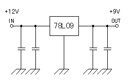 The circuit this time is using the various oscillators. The frequency of those oscillators is related with the measurement precision. So, the power supply voltage to use must be stable. Because the circuit is using the CMOS, the power supply voltage is OK rather than +5 V. The inner power supply voltage is made +9 V by the 3 terminal regulator. The input voltage is using about +12 V voltage in the relation with relay drive voltage. |

