Diodes
|
A diode is a semiconductor device which allows current to flow through it in only one direction. Although a transistor is also a semiconductor device, it does not operate the way a diode does. A diode is specifically made to allow current to flow through it in only one direction. Some ways in which the diode can be used are listed here. This symbol 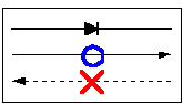 The meaning of the symbol is (Anode) Current flows from the anode side to the cathode side. Although all diodes operate with the same general principle, there are different types suited to different applications. For example, the following devices are best used for the applications noted. 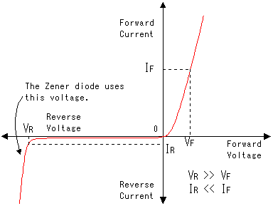 The graph on the right shows the electrical characteristics of a typical diode. When a small voltage is applied to the diode in the forward direction, current flows easily. Because the diode has a certain amount of resistance, the voltage will drop slightly as current flows through the diode. A typical diode causes a voltage drop of about 0.6 - 1V (VF) (In the case of silicon diode, almost 0.6V) This voltage drop needs to be taken into consideration in a circuit which uses many diodes in series. Also, the amount of current passing through the diodes must be considered. When voltage is applied in the reverse direction through a diode, the diode will have a great resistance to current flow. Different diodes have different characteristics when reverse-biased. A given diode should be selected depending on how it will be used in the circuit. The current that will flow through a diode biased in the reverse direction will vary from several mA to just µA, which is very small. The limiting voltages and currents permissible must be considered on a case by case basis. For example, when using diodes for rectification, part of the time they will be required to withstand a reverse voltage. If the diodes are not chosen carefully, they will break down. 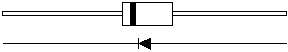 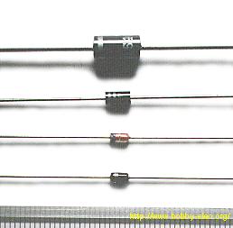 The stripe stamped on one end of the diode shows indicates the polarity of the diode. The stripe shows the cathode side. The top two devices shown in the picture are diodes used for rectification. They are made to handle relatively high currents. The device on top can handle as high as 6A, and the one below it can safely handle up to 1A. However, it is best used at about 70% of its rating because this current value is a maximum rating. The third device from the top (red color) has a part number of 1S1588. This diode is used for switching, because it can switch on and off at very high speed. However, the maximum current it can handle is 120 mA. This makes it well suited to use within digital circuits. The maximum reverse voltage (reverse bias) this diode can handle is 30V. The device at the bottom of the picture is a voltage regulation diode with a rating of 6V. When this type of diode is reverse biased, it will resist changes in voltage. If the input voltage is increased, the output voltage will not change. (Or any change will be an insignificant amount.) While the output voltage does not increase with an increase in input voltage, the output current will. This requires some thought for a protection circuit so that too much current does not flow. The rated current limit for the device is 30 mA. Generally, a 3-terminal voltage regulator is used for the stabilization of a power supply. Therefore, this diode is typically used to protect the circuit from momentary voltage spikes. 3 terminal regulators use voltage regulation diodes inside. 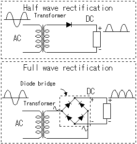 Rectification diodes are used to make DC from AC. It is possible to do only 'half wave rectification' using 1 diode. When 4 diodes are combined, 'full wave rectification' occurrs. Rectification diodes are used to make DC from AC. It is possible to do only 'half wave rectification' using 1 diode. When 4 diodes are combined, 'full wave rectification' occurrs.Devices that combine 4 diodes in one package are called diode bridges. They are used for full-wave rectification. 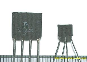 The photograph on the left shows two examples of diode bridges. The cylindrical device on the right in the photograph has a current limit of 1A. Physically, it is 7 mm high, and 10 mm in diameter. The flat device on the left has a current limit of 4A. It is has a thickness of 6 mm, is 16 mm in height, and 19 mm in width. 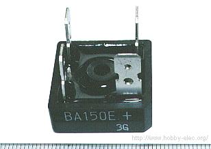 The photograph on the right shows a large, high-power diode bridge. It has a current capacity of 15A. The peak reverse-bias voltage is 400V. Diode bridges with large current capacities like this one, require a heat sink. Typically, they are screwed to a piece of metal, or the chasis of device in which they are used. The heat sink allows the device to radiate excess heat. As for size, this one is 26 mm wide on each side, and the height of the module part is 10 mm. 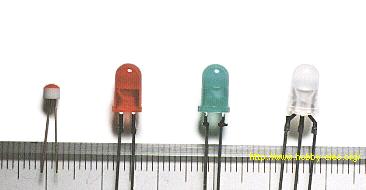 Light emitting diodes must be choosen according to how they will be used, because there are various kinds. The diodes are available in several colors. The most common colors are red and green, but there are even blue ones. The device on the far right in the photograph combines a red LED and green LED in one package. The component lead in the middle is common to both LEDs. As for the remaing two leads, one side is for the green, the other for the red LED. When both are turned on simultaneously, it becomes orange. When an LED is new out of the package, the polarity of the device can be determined by looking at the leads. The longer lead is the Anode side, and the short one is the Cathode side. The polarity of an LED can also be determined using a resistance meter, or even a 1.5 V battery. When using a test meter to determine polarity, set the meter to a low resistance measurement range. Connect the probes of the meter to the LED. If the polarity is correct, the LED will glow. If the LED does not glow, switch the meter probes to the opposite leads on the LED. In either case, the side of the diode which is connected to the black meter probe when the LED glows, is the Anode side. Positive voltage flows out of the black probe when the meter is set to measure resistance. 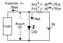 It is possible to use an LED to obtain a fixed voltage. The voltage drop (forward voltage, or VF) of an LED is comparatively stable at just about 2V. I explain a circuit in which the voltage was stabilized with an LED in "Thermometer of bending apparatus-2". 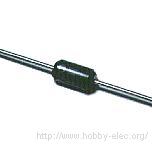 Diodes are used to rectify alternating current into direct current. However, rectification will not occur when the frequency of the alternating current is too high. This is due to what is known as the "reverse recovery characteristic." Diodes are used to rectify alternating current into direct current. However, rectification will not occur when the frequency of the alternating current is too high. This is due to what is known as the "reverse recovery characteristic."The reverse recovery characteristic can be explained as follows: IF the opposite voltage is suddenly applied to a forward-biased diode, current will continue to flow in the forward direction for a brief moment. This time until the current stops flowing is called the Reverse Recovery Time. The current is considered to be stopped when it falls to about 10% of the value of the peak reverse current. The Shottky barrier diode has a short reverse recovery time, which makes it ideally suited to use in high frequency rectification. The shottky barrier diode has the following characteristics. |