|
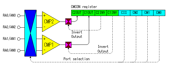
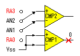
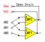
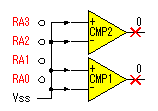
There is analog voltage comparator function in PIC16F628. PIC16F628 has 2 circuits of this function. It has a function to compare two in the voltage which is inputted to RA3 from RA0 and a function to compare with the reference voltage. It is possible to make interruption occur when either comparator output is changed. In the case, it makes set the CMIE bit of the PIE1 register to "1". Also, it should set the PEIE bit and the GIE bit of the OPTION register to "1". By this, when the output of the comparator is changed, "1" is set to the CMIF bit of the PIR1 register and the interruption occurs. In the interruption processing, CMIF of the PIR1 register must be cleared. The interruption always occurs when the output of the comparator doesn't change when not doing this. The output of the comparator is put to C1OUT and the C2OUT bit of the CMCON register. The output contents of C1OUT and C2OUT can be reversed by the setting of C1INV and C2INV bit. The example of CMP1 is shown below. CMP2 is same too.
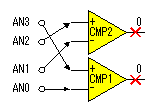
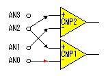
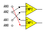
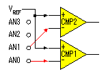
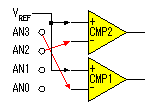
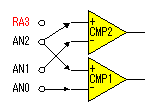
The input to the comparator can be controlled by CM2 from CM0 and CIS bit of the CMCON register. In the condition immediately after the turning on, all CM2, 1, 0 and CIS are in the condition of "0". In this condition, the port of RA0-3 is set as the analog port of AN0-3. When not using a comparator, all CM2, 1, 0 must have been set to "1" by the initialization processing. CIS is the initial of Comparator Input Switch. It is used when switching the analog port and comparing more than one analog signal. When CM2-0 is "010", a maximum of four kinds of analog signals can be compared with the reference voltage with two comparators by changing in CIS. For the details, refer to the manual of PIC16F628. The combination of each bit is as follows.
PIC16F628 has the circuit which makes reference voltage. This function is an independent circuit with the comparator. However, when making CM2-0 "010", voltage which was made with reference voltage circuit is applied to the positive input terminal of each comparator. The output of the reference voltage can be output at the RA2 port by the setting of VRCON register. The reference voltage can be designated by 4 bits of VR3-0 of the VRCON register. The range which can be specified is 16 steps from 0 to 15. There are two ranges of low voltage range and high-voltage range. In case of the high voltage, the maximum is about 3.6 V. It is possible to do the setting of the voltage range by the VRR bit of the VRCON register. Reference voltage is calculated by the following formula.
Resistance and Voltage Relationship in case of VDD = 5V
|