Asynchronous communication of PIC16F873 (USART)
|
On this page, I will explain about USART(Addressable Universal Synchronous Asynchronous Receiver Transmitter) which is one of the two communication ports equipped with PIC16F873.
The USART can be used following communicate mode.
Generally, in the communication of the USART, one data block is composed of 8 bits. The USART module also has a multi-processor communication capability using 9-bit address detection. On this page, I will explain about Asynchronous mode communication.
The circuit of the condition not to transfer data is H level. When becoming an L level(Start bit) from this condition, the receiving side recognizes that the data transfer begins. After that, according to the signaling speed, the transfer of the data is done. The transfer of the block ends when a stop bit (H level) is detected last. A signaling speed is controlled by the timer which is independent in the sender and the receiving side. So, it isn't possible to do correct communication when there is an error in this timer. In the asynchronous mode communication of USART, the RX port is used for receiving and the TX port is used for the transmission, so, it is possible to send and receive at the same time. (Full duplex) 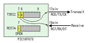 In the asynchronous mode, it uses RC6/TX/CK (17 pins) for the data transmission and RC7/RX/DT (18 pins) is used for the data receiving. The mode of the input/output of the TX port, the RX port must be set to the TRISC register to use a USART. Bit 6 of C port is set to output mode (0) and bit 7 is set to input mode (1). In the asynchronous mode, it uses RC6/TX/CK (17 pins) for the data transmission and RC7/RX/DT (18 pins) is used for the data receiving. The mode of the input/output of the TX port, the RX port must be set to the TRISC register to use a USART. Bit 6 of C port is set to output mode (0) and bit 7 is set to input mode (1).To use RC6 and RC7 as the USART port, the SPEN bit of the RCSTA register must be made "1".
BRG is controlled by the SPBRG register. It is the register to control a free run timer with byte. In case of asynchronous mode, BRGH bit of the TXSTA register is used for the control of the signaling speed too. When writing a value in the SPBRG register, BRG timer is reset. The clock frequency of the PIC and signaling speed can be calculated by the following formula.
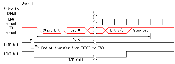
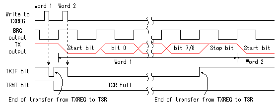
For the details of the value of the SPBRG register, refer to "SFR explanation for PIC16F873(17)". 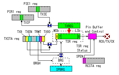 When doing an asynchronous transmission with the USART, it makes the SPEN bit of the RCSTA register "1" and it makes RC6 port as TX port. When doing an asynchronous transmission with the USART, it makes the SPEN bit of the RCSTA register "1" and it makes RC6 port as TX port.When loading a transmit data to the TXREG register, it is transferred to the TSR(Transmit Shift Register) by the hardware and it is transmitted from the TX port. The transmission of the data is done by setting the TXEN bit of the TXSTA register. LSb(Least Significant bit) is transmitted first. When the contents of the TXREG are sent to the TRS, the TXIF bit of the PIR1 register becomes "1" and the interruption occurs. But, the TXIE bit of the PIE1 register must become "1". This interruption means that the contents of the TXREG has been sent to the TSR and it becomes the condition that it is possible to load data in the TXREG. The data can be continuously transmitted if detecting this interruption and setting the following data to the TXREG.(Back to Back) The TXIF bit can not be cleared in software. The TXIF bit is cleared when data is loaded in the TXREG. The TRMT bit of the TXSRA register is set to "1" when the data of the TSR register is transmitted. This bit doesn't have an interruption logic. So, to confirm the empty of the TSR register, you should poll TRMT bit periodically. Because the TSR register is not mapped in data memory, you can not read/write the contents of this register directly. A signaling speed is controlled by BRG(Baud Rate Generator). Parity is not supported by the hardware, but can be implemented in software ( and stored as the ninth data bit ). In the case, ninth bit as parity is transmitted by setting parity bit contents to the TX9D bit of the TXSTA register and setting the TX9 bit. The TX9D bit must be set before setting the data to TXREG. A transmission is started as soon as loading data in the TXREG. It isn't normally transmitted when the ninth bit isn't set to TX9D before it. When clearing TXEN bit while transmitting data, a transmitter is reset and the RC6/TX/CK pin becomes a high impedance condition.
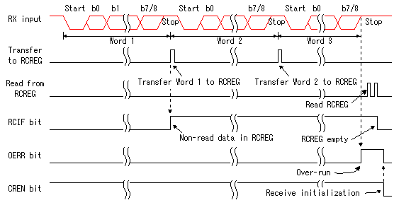
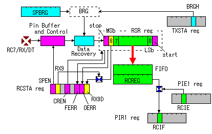 When doing an asynchronous transmission with the USART, it makes the SPEN bit of the RCSTA register "1" and it makes RC7 port as RX port. When doing an asynchronous transmission with the USART, it makes the SPEN bit of the RCSTA register "1" and it makes RC7 port as RX port.The data which was received at the RX port is received with the RSR register through the Data recovery circuit. Data at the RX port is sampled three times to do the judgment of the H level or the L level. A received data is stored in the RSR register according to the signaling speed which is specified by the SPBRG register and the BRGH bit of the TXSTA register. When detecting a stop bit, the contents of the RSR register are transferred to the RCREG register. The RCIF bit of the PIR1 register is set when data is stored in the RCREG register and the interruption occurs. To make interruption occur, the RCIE bit of the PIE1 register must be set beforehand. The RCREG register is composed in two FIFO(First In First Out) buffers and can store data for 2 block. This is the protection when delay in the reading processing by the software. RCIF bit is read only bit and is cleared with the hardware when all RCREG registers are read. If both RCREG registers are full(It isn't read) when the receiving completes with the RSR register, the OERR bit of the RCSTA register is set and the occurring of the overrun error is expressed. The data which was stored in the RSR register at this time is lost. Also, receiving operation isn't done. It clears the CREN bit of the RCSTA register once and it sets to return this condition normally again. By this operation, OERR bit is cleared. The FERR bit of the RCSTA register is set when the frame error detects with the RSR register. The RX9D bit and the FERR bit which is stored in the RCSTA register are rewritten every time it receives data in 1 block. So, the FERR bit of the RCSTA register must be checked before reading the contents of the RCREG register. When receiving a normal frame behind the error frame, the information of FERR disappears. So, the normality of the received data can not be judged.
The operation is as follows. This operation is effective in case of 9-bit transfer. Set RX9 bit and ADDEN bit of the RCSTA register. In this way, only when the data of the 9th bit is "1", received data is stored in the RCREG register. The data that the 9th bit is "0" isn't stored. 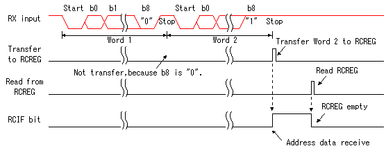 |
|||||||||||||||||||||||||||||||||||||||||||||||||||||||
