Integrated Circuits
|
An integrated circuit contains transistors, capacitors, resistors and other parts packed in high density on one chip. Although the function is similar to a circuit made with separate components, the internal structure of the components are different in an integrated circuit. The transistors, resistors, and capacitors are formed very small, and in high density on a foundation of silicon. They are formed by a variation of printing technology. There are many kind of ICs, including special use ICs. 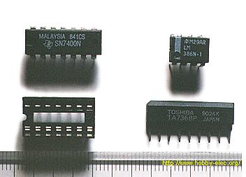 The top left device in the photograph is an SN7400. It contains 4 separate "2 input NAND" circuits. There are 7 pins on each side, 14 pins total. ICs in this form are called Dual In line Package (DIP). When an IC has only one row of pins, it os called a Single In line Package (SIP). The number of pins changes depending on the function of IC. At the bottom left is an IC socket for use with 14 pin DIP ICs. ICs can be attached directly to the printed circuit board with solder, but it's better to use an IC socket, because you can easily exchange it should the IC fail. On the top right is an LM386N audio amplifier. It can be used for amplification of low frequency, low power signals. IT has 8 pins and the maximum output is 660mW. On the bottom right is a TA7368P, which also is for amplification of low frequency electric power. It has a maximum output of 1.1 watts. It is a 9 pin SIP IC. Below, the most common ICs are shown. (Those parts that I use most.) For extensive details on each part, see the corresponding data sheet. The part numbers of the SN74 series ICs are written with a 74, often followed by LS or HC. LS (Low power Shottky) indicates low power consumption. HC indicates the device is High speed C-MOS (Complementary-Metal Oxide Semiconductor), and is also a low power consumption IC. The average current consumption for each type of chip is listed below. The current shown is for when the device is in a LOW state output. In the case of the LOW state output, current consumption is much greater than in the HIGH state output.
Several kinds of ICs are not available in the LS or HC type. For example, SN7445 is not available in LS or HC. It is available only as SN7445, the normal type.
It is very easy to get stabilized voltage for ICs by using a three terminal voltage regulator. The power supply voltage for a car is +12V - +14V. At this voltage, some ICs can not operate directly except for the car component ICs. In this case, a three terminal voltage regulator is necessary to get the required voltage. The three terminal voltage regulator outputs stabilized voltage at a lower level than the higher input voltage. A voltage regulator cannot put out higher voltage than the input voltage. They are similar in appearance to a transistor. 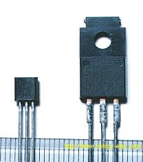 On the left in the photograph is a 78L05. The size and form is similar to a 2SC1815 transistor. The output voltage is +5V, and the maximum output current is about 100mA. The maximum input voltage is +35V. (Differs by manufacturer.) On the right is a 7805. The output voltage is +5V, and maximum output current is 500mA to 1A. (It depends on the heat sink used) The maximum input voltage is also +35V. There are many types with different output voltages. 5V, 6V, 7V, 8V, 9V, 10V, 12V, 15V, 18V Because the component leads differ between kinds of regulators, you need to confirm the leads with a datasheet, etc.  Example of 78L05 Part number is printed on the flat face of the regulator, and indicates the front. Right side : Input Center : Ground Left side : Output  Example of 7805 Part number is printed on the flat face of the regulator, and indicates the front. Right side : Output Center : Ground Left side : Input Opposite from 78L05. |
 Front View