[Menu]>[Electronic circuit engineering introduction]>[Assembly process]
Circuit operation explanation
of astable multivibrator


 About the inverter IC
The inverter has one piece of the input and one piece of the output.
The input level( high level or the low level ) and the output level of the inverter become always opposite.
The TTL is the abbreviation of Transistor Transistor Logic. Basically, it shows the condition at the voltage of 0 V and +5 V.
0 V are called the Low level( It sometimes expresses by the L or 0 ) and +5 V are called the High level( It sometimes expresses by the H or 1 ).
| Input | Output |
0(L) | 1(H) |
1(H) | 0(L) |
When the input changes from 0 V to +5 V gradually, as for the output, there is not a change with it.
When the input voltage exceeds some voltage, the output makes the change the opposite condition rapidly. This voltage is called "Threshold Input Voltage". The symbol writes VT.
When the input terminal of the inverter is in the opening condition, the voltage of the input terminal becomes above the threshold voltage. The inverter output in this condition becomes the L condition.
The threshold voltage depends on the kind of IC. The following table is the value which I measured.
It is not the one which is written on data sheet.
|
VCC=+5V
Threshold
Input Voltage | 7404 | 74LS04 |
74HC04
(Reference) |
| VT(V) | 0.7 to 1.4 | 1.0 to 1.4 | 2.5 to 2.6 |
|
The higher voltage is the input voltage when the output voltage finishes falling. |
Generally, the digital logic circuit handles 0V(L) or +5V(H). So, there is not to be conscious too much of the threshold voltage which is the voltage of the middle.
In the case like the multi-vibrator this time, the threshold voltage influences because the input changes analog-ly (continuous).
The equivalent circuit
The equivalent circuit shows the circuit composition when putting together the function of the IC with electronic parts of the transistors, the diodes, the resistances, the capacitors and so on. Actually, the such device isn't incorporated and shows the equal function.
The equivalent circuit depends on the kind in the inverter IC.
The equivalent circuit which is on data sheet is shown below as the reference. As for the other IC, see the data sheet.
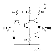 | 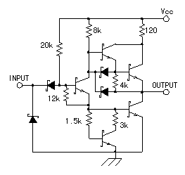 |
7404 | 74LS04 |
 The absolute rating The absolute rating
| Item | 7404 | 74LS04 |
74HC04
(Reference) |
|
Supply voltage(V)
Vcc | 7 | 7 | 7 |
Input voltage(V) | 5.5 | 5.5 | Vcc + 1.5 |
|
Operating temp
(°C)
(Package surface) | 0 to 70 | 0 to 70 | -40 to +85 |
If it exceeds these rated values, the IC has broken. |
|
 The input/output electric current characteristic The input/output electric current characteristic
| Item | 7404 | 74LS04 |
74HC04
(Reference) |
Input current
characteristic | H  | 40uA | 20uA | - |
L  | 1.6mA | 0.4mA | - |
Output current
characteristic | H  | 0.4mA | 0.4mA | 4mA |
L  | 16mA | 8mA | 4mA |
In the input current characteristic, "H  " is the electric current value which flows when the input becomes high level. " is the electric current value which flows when the input becomes high level.
In the input current characteristic, "L  " is the electric current value which pours when the input becomes low level. " is the electric current value which pours when the input becomes low level.
In the output current characteristic, "H  " is the limit electric current value which it is possible to draw off when the output becomes high level. " is the limit electric current value which it is possible to draw off when the output becomes high level.
In the output current characteristic, "L  " is the limit electric current value which it is possible to pour when the output becomes the low level. " is the limit electric current value which it is possible to pour when the output becomes the low level.
Because it is, when connecting 7404 pieces of the output with other 7404 pieces of the input, it is possible to connect in the 10.
In case of 74LS04, it is possible to connect in the 20.
When connecting with the IC of the other kind, it depends on the characteristic of the IC.
It doesn't break if being little even if it crosses the value of the input/output electric current characteristic. It breaks when short-circuiting and doing the extreme thing in the output.
The operation when crossing the standard value isn't guaranteed.
74HC04 is made with CMOS(Complementary MOS) and the input electric current flows hardly.
It is explained by the following circuit operation but because the input electric current must flow little at the circuit this time, 74HC04 can not be used. |

 The operation explanation of the multi-vibrator circuit
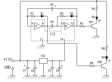
First, I assume that the input (the 9th pin) of the inverter A is the low level. At this time, the output (the 8th pin) of the inverter A becomes high level.
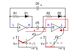
If supposing that the electric charge isn't stored up in C5, the electric current flows with the inverter A output  C5
C5  R2
R2  D2
D2  inverter B output.
At first, the condition of the inverter B is unsettled but because the output of the inverter B is not totally in the high level condition, above-mentioned electric current flows.
When the electric charge begins to store up in C5, C5 can be seen like the short circuit condition. Because it is, the input of the inverter B becomes the high level condition. The output of the inverter B becomes the low level and above-mentioned electric current route is totally formed by this operation.
However, because it is a small amount (being 40uA like the above table), most of the electric currents flow in the route which passes R2.
When the electric charge is stored up in C5, the electric current decreases. Input voltage of the inverter B, too, goes down with it and approaches the threshold voltage of the inverter B. Because the output of the inverter B is the low level (being 0V almost), the electric current alwayses fall through more through R2, D2 and the input voltage of the inverter B becomes the threshold voltage (VT).
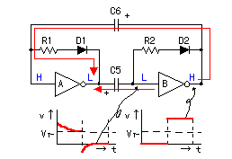
Then, the output of the inverter B reverses and becomes the high level condition.
When the output of the inverter B becomes high level, the voltage of cathode side of D2 becomes high and the electric current which passes R2 stops.
The output of the inverter B is conveyed to the input of the inverter B through R2 when there is not D2. Then, it repeats the operation that the input of the inverter B becomes high level again and that the output becomes the low level and the inverter B has worked in the oscillation.
The high level output of the inverter B makes the input of the inverter A the high level condition through C6. At this time, the electric current flows with the inverter B output  C6
C6  R1
R1  D1
D1  inverter A output.
When the input of the inverter A becomes the high level condition, the output of the inverter A becomes the low level. The electric charge that the side of the output of the inverter A is positive already is stored up in C5. Because the output of the inverter A becomes the low level (0V) in the condition, the voltage on the side of the input of the inverter B starts from the negative potential.
The discharge of the electric charge of C5 is done in electric current's flowing through the inverter B input  C5
C5  inverter A output.
When the electric charge is stored up in C6, the electric current decreases and input voltage of the inverter A goes down. When the input voltage of the inverter A becomes the threshold voltage, the output of the inverter A becomes high level.
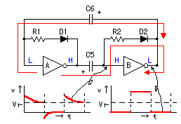
In this, it returned to the first condition of the explanation.
After that, the circuit repeats this operation.
There may be question here.
First, it made the input of the inverter A the low level.
When turning on, the condition of the inverter isn't decided. Each inverter characteristic isn't the same. The output of either the inverter becomes high level earlier and it fixes the condition. When there is an ideal inverter circuit, it is possible to think of repeat's not being worked, too. However, actually, there is not such one and it works repeatedly.
Discharging by C5, C6
After the inverter is turned, C5 or C6 must discharge (missing the electric charge).
With this discharge, the electric current which pours off the inverter input becomes necessary.
When it isn't possible to do this discharge, at the next period, because the electric charge starts from the stored condition, the input voltage of the invertor becomes the threshold voltage immediately. That is, the period of the repeat becomes short or the repeat isn't done.
The period doesn't sometimes become long without discharge's being sufficiently done even if it makes the value of the capacitor big to make the repeat period long, too.
When using 74HC04 as the inverter, because the input electric current flows hardly, the discharge isn't done and doesn't do the normal operation.
Indeed, I attempted to work the circuit using 74HC04. At first, seemingly, it did the normal operation, but both LEDs lit up at the same time and didn't do the normal operation in case of being for a while.
 The calculation of the repeat period
The period with the turning inverter is decided by the capacitor (C), the resistance (R) and the threshold voltage (VT).
Strictly, it changes more with the discharge situation of C, too.
In case of the inverter A, C6 and R1 are related and in case of the inverter B, C5 and R2 are related.
The electric current change when the voltage (V) is applied to the circuit which the capacitor (C) and the resistor (R) were connected with in series can be demanded by the following formula.
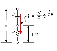
i = (V/R)e-(t/CR)
| i | : | The electric current which changes in the time |
| V | : | The applied voltage |
| R | : | The resistance value |
| e | : | The base of the natural logarithm(2.71828) |
| t | : | The elapsed time after the charging beginning |
| CR | : | The capacitive time constant (C x R) |
The change of the voltage which is applied by the both edges of the resistor (R) becomes the following formula.
iR = Ve-(t/CR)
The time that this value becomes equal to the VT becomes the reversing time of the inverter.
VT = Ve-(t/CR)
In the reversing time (t), it becomes the following formula.
t = -CR ln(VT/V)
It attempts to adapt the actual value.
The value of the logarithm see the logarithm table.
C = 470µF = 470 x 10-6F
R = 1Kohm = 1 x 10³ohm
V = 4.5V
VT = 1.4V (The input voltage when the output voltage finishes falling)
| t | = | -(470 x 10-6) x (1 x 103) x ln(1.4/4.5) |
| = | -(470 x 10-3) x ln(0.31) |
| = | -(470 x 10-3) x (-1.17) |
| = | 550 x 10-3 |
| = | 0.550 seconds |
|
When making the VT=1.0 V (Input voltage when the output voltage begins to fall)
The other parameter is the same as the above condition.
| t | = | -(470 x 10-6) x (1 x 103) x ln(1.0/4.5) |
| = | -(470 x 10-3) x ln(0.22) |
| = | -(470 x 10-3) x (-1.51) |
| = | 710 x 10-3 |
| = | 0.710 seconds |
When measuring the period of the actual circuit, the red LED (the green is the same) lights up the 45 times to the 1 minute.
Because t was the time with the half period, it was to be in the 0.667 seconds at the 60sec/90.
The main cause when the period doesn't suit the computation result includes the following.
Discharging
of the capacitor | When to discharge of the capacitor isn't done, the time which reaches the threshold voltage becomes short. |
| V |
The high level voltage of the inverter output influences.
The circuit this time is passing the electric current which is bigger than the rating because of the transistor drive.
In the measurement, it becomes about 4.5 V.
When this voltage becomes low, the period becomes short. |
| VT |
It depends on the kind of the IC.
The lower this voltage is, the longer the period becomes. |
The voltage drop
of the diode |
The voltage drop of the diode influences.
With the electric current which flows through the diode, the voltage drop occurs with the diode.
The bigger this value is, the shorter the period becomes. |


