Parts explanation
of the thermostat
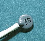 This is the thermistor which was used this time. It is doing a disk type in D-53 which is made by NEC. The lead line which isn't insulated is put to the body of the thermistor. Because it is, when using, the lead wire must be insulated with the endured insulating material to the high temperatures such as the glass fiber tube. As for the size of the thermistor, the diameter of the disk is 7 mm and the thickness is 2 mm. 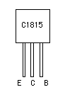 This transistor is used with the thermistor voltage converter and the relay drive circuit. In case of the thermistor voltage converter, hFE becomes an important factor. I used Y type as the class of hFE. 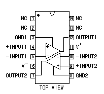 I used LM319 as the voltage comparator. The other comparator is OK. I think that the comparator which has a hysteresis characteristic suits more. As for the way of making have the hysteresis characteristic using the resistor, refer to "Circuit explanation of the temperature controller of the bending apparatus". 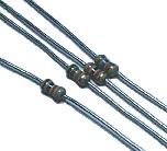 As for the resistors to be using with the circuit this time, all 1/8 W are used. 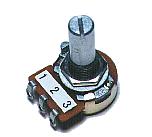 This is the variable resistor to set the temperature. I used the 10-kohm one but the one with the other value is OK. The resistor which has the B-type change curve is used. 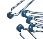 These are the capacitors to bypass the alternating current signal which is applied to the input of the voltage converter and the comparator to the ground. At the circuit this time, the alternating current signal is the unnecessary signal which becomes the malfunction of the equipment. I used the multilayer ceramic capacitors for the bypass capacitors. 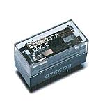 I used G2VN-237 P which is made by the OMRON company. The other relay is OK. When using a power relay, to drive a small relay with the relay drive circuit and to control a power relay by the point of contact is safer. 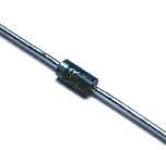 Because it is, when making the relay the OFF condition, the high voltage sometimes occurs. This diode is put to protect for this voltage not to break the transistor. This time, because the power supply voltage isn't high, even if it doesn't put this diode, the transistor doesn't break. I put for the safety. 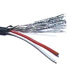 With the cable between the thermistor and the thermostat, the one which used a shielded wire is safer. When the distance isn't long, it is OK with the pair cable. This time, I used the shielded wire with 2 wires. 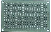 I used the one of 15 halls x 25 halls. The universal printed board 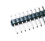 This is the terminal to connect the cable of the input and the output. It is not necessary to use the one of this shape. Also, if connecting the wire with direct to the printed board, it is not necessary to use this terminal. 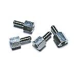 I use this to install the printed board to the case. There is not necessity of the metal. I used the one with the 5-mm height for the 3-mm screw. |