Circuit explanation
of the temperature controller
of the bending apparatus
|
The circuit to be using with the temperature controller is the circuit which combined "Thermostat" and "Electric power controller" to be introducing in "Electronic Circuit Beans Collection". At first, I made the temperature detector and the electric power control circuit on one printed board. However, the much induction with the alternating voltage occurred and the relay vibrated like the buzzer at the time of ON/OFF of the electric power control circuit. Therefore, I divided those circuits into two sheets of the printed boards. At the equipment this time, the temperature control circuit which used the thermistor to control the temperature of the generation of heat by the nichrome wire is used. The resistance value of the thermistor falls when the temperature rises. This characteristic is used for the temperature detection. The practicable temperature of the thermistor is from 100°C to 140°C generally. This temperature depends on the thermistor. This time, the temperature to want to control is about 160°C. Because it is, so as not to exceed the upper limit temperature, the thermistor is installed in the place which left the heating element a little. When separating the thermistor with the heating element, it isn't possible to do the correct temperature control by the outside condition. However, because to control so correctly wasn't necessary for the purpose this time, I thought that it became the practical use sufficiently. However, this was to do failure being. The temperature change range in the exothermic part had become big. The temperature control circuit is detecting the resistance value change of the thermistor using the voltage amplifier. Because the circuit this time is used near the AC circuit the output of the voltage comparator sometimes vibrates by the induction of the alternating current. Therefore, I decided to make the voltage comparator have the hysteresis characteristic. 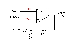 I connected the output of the voltage comparator with the positive input terminal through the resistor (Rf). I connected the output of the voltage comparator with the positive input terminal through the resistor (Rf).When the negative input of the voltage comparator becomes higher than the voltage of the positive input, the output becomes the about 0 volts. When the output becomes the about 0 volts, through Rf, the positive input voltage is lowered and the potential difference with the negative input becomes big. Even if a little voltage of the negative input falls, the output doesn't change. It is same when negative input voltage goes down, too. The output voltage rises when the negative input becomes below the positive input. Then, the positive input voltage is more rised by Rf. That is, the difference is made to the input voltage for the output voltage to change. This is the hysteresis characteristic. 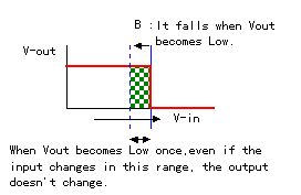 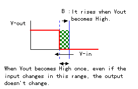 The switching power supply which was used this time doesn't have the good output characteristic. The 12-V voltage does the several-millivolt change by ON/OFF of the relay. The voltage comparator to be using for the temperature detection is detecting the minute voltage change of the mV unit. So, when the power supply changes, it isn't possible to do the normal temperature detection. Indeed, the phenomenon that the relay repeats ON/OFF near the setting temperature occurred. After investigating, the change of the power supply was to do cause being. As the measure, I made the power supply of the temperature detector the stable voltage of 9 V using the 3 terminal regulator. With this, that the relay repeated ON/OFF passed away. The operation point of the transistor which changes the resistance value of the thermistor into the voltage changes by making the power supply of the temperature detector 9 V. So, the value of the resistor to be putting in the thermistor in series must be once more adjusted. 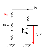 I adjusted the operation point of the transistor as follows. It connects the resistor of 1K-ohm with the base of the transistor. It puts the resistor Rx between 1K-ohm and the power supply. It adjusts the value of Rx for the collector voltage of the transistor to become about 1 V. The resistor of 1K-ohm is instead of the resistance value of the thermistor at about 100°C. In my adjustment, Rx was 12K-ohm and became the exactly good value. For the details of the temperature control circuit by the thermistor, refer to "Thermostat". At the equipment this time, the 300-W nichrome wire is used. When heating this nichrome wire at the maximum electric power, it becomes the high temperature which is more than necessary . When becoming the setting temperature with the temperature controller, the supply of electric power to the nichrome wire is stopped. The equipment this time is made to be able to adjust the supply of electric power at the time of the temperature rise and fall to make the temperature be stable. It switches two sets of the resistors for ON(For the temperature rise) and OFF(For the temperature fall) with the relay of the temperature controller. Actually, I think that it is unnecessary to OFF. It is the idea pass a little. The triac is installed on the aluminum case for radiation. I am installing it on the case for the safety. The LED with the 2 colors is used to understand the condition of the electric power control. As for the red, it displays the electric power ON condition and as for the green, it displays the electric power OFF condition. This lamp combines the indicating lamp, too. For the details of the electric power control circuit which used the triac, refer to "Electric power controller". |