Parts explanation
for +5V Switching regulator (1)
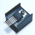
 This is the regulator which converts the 12V input voltage to the 5V voltage. This regulator is for the positive power supply. There is a series of the regulator which the output voltage can be changed to in the range from 1.3 V to 37 V but this time, I am using the one of the 5 V fixation. 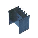 In case of the switching regulator, there is comparatively little electric power to lose with the regulator. It is the about 1.5 W loss when passing the 1 A output current. In the one which was made this time, it was about 1 W loss. It seems that it is OK even if it doesn't put the heatsink but I put the small one for the safety. The size of the heatsink which I used this time is hereinafter. The 25-mm height, the 23-mm width of the surface which installs the regulator and the 10-mm depth to the direction of fin. 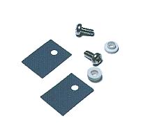 The back plate (the part which puts the heatsink) of the regulator is connected with the ground pin. You may put the regulator to the heatsink to direct if the heatsink doesn't touch the electric circuit. I place the insulating material among them. It uses the 3mm screw to install the regulator at the heatsink. However, the about 4mm hole is opened at the regulator. This is because the screw makes not touch to the regulator, putting the circular insulation part to the hole of the regulator. You had better buy beforehand with the silicon rubber.
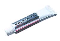 The silicon rubber is put between the regulator and the heatsink but the silicon grease is put in the thermal conductivity to improve. The silicon grease is the compounding of the white grease. The metallic oxide is mixed by it to improve the thermal conductivity.The silicon grease is painted the both sides of the silicon rubber and improves the heat conduction between the regulator and the heatsink. You don't need to paint a lot of it. There is not an effect in the part which was stuck out of the rubber. 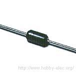 LM2575 switches the electric current at 52 kHz. At this frequency, it isn't possible to use the diode for the ordinary rectifier because the reverse recovery time is long. As the current-carrying capacity, it uses more than 1.5 times of ones of the output current. The diode which was used this time is ERB81-004(VRRM=40V,IO=1.7A) which is made by Fuji Electric. 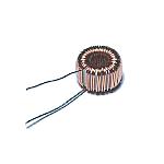 I used the toroidal coil for the inductor. The toroidal coil is the one to have wrapped the copper wire around the cylindrical core. It is possible to make that the magnetic flux which occurs with the coil doesn't leak out outside, that the coil efficiency is good and that the magnetic flux has an influence on the others little. You can make it, but it is terrible to roll up the copper wire. There is a chart which looks for the value of the inductor at the data sheet of LM2575. When the output is 1 A in the 12-V input, the inductor is 220 µH. This time, I used the coil of 125 µH, 2 A. The ripple may increase little.  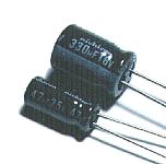 You use the capacitor of few ESR(Equivalent Series Resistance) for the ripple filter capacitor of the output. The capacitor has the inductance and the resistance as well as the capacitance. This resistance is the ESR. When the value of the ESR is big, it generates heat with the electric current which flows through the capacitor. The big electric current flows through the capacitor to use with the ripple filter circuit of the switching regulator. Because it is, the capacitor which has the big ESR is heated. 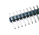 This is the terminal to connect the cable of the input and the output. It is not necessary to use the one of this shape. Also, if connecting the wire with direct to the printed board, it is not necessary to use this terminal. 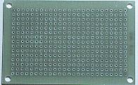 I was irresolute about whether or not to use the printed board or the universal printed board when I made the circuit this time. I decided to use the universal printed board from the easiness of the creation. I used the one of 15 halls x 25 halls. The universal printed board 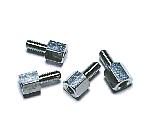 I use this to install the printed board to the case. There is not necessity of the metal. |