Coils
|
A coil is nothing more than copper wire wound in a spiral. This symbol Inductance value is designated in units called the Henry(H). The more wire the coil contains, the stronger its characteristics become. The inductance value can become quite large. If a coil is wound around an iron rod, or ferrite core (strengthened with iron powder), the inductance of the coil will be greatly increased. Coils used in typical electric circuits varely widely in values, ranging from a few micro-henry (µH) to many henry (H). Coils are sometimes called "inductors." Inductance is the measure of the strength of a coil. Capacitors have capacitance, resistors have resistance, and Inductors (coils) have inductance. When alternating current flows through a coil, the magnetic flux that occurs in the coil changes with the current. When a second coil is put close to the first coil (with the changing flux), alternating voltage is caused to flow in the second coil by an effect known as "mutual induction." Mutual inductance (inductance) is measured in units of the Henry. The changing magnetic flux in a coil affects itself as well as other coils. This is called self induction, the degree of this self induction is called Self Inductance. Self inductance is a measure of a coil's ability to establish an induced voltage as a result of a change in its current. Self inductance is commonly referred to as simply "inductance," and is symbolized by "L". The unit of inductance is the Henry (H). The definition of "Henry" is "When a current of 1 ampere flows through a given coil in 1 second such that 1 volt is induced to flow in a second coil, the mutual inductance between the coils is said to be 1 Henry." The definition of self inductance is the same, except that the 1 volt is induced in the first coil; there is no second coil. When wire is coiled, it takes on various characteristics that are different from straight wire. Below I will explain some of the characteristics coils that I know. When current begins to flow in the coil, the coil resists the flow. When current decreases, the coil makes current continue to flow (briefly) at the previous rate. This is called "Lenz's law". 'The direction of induced current in a coil is such that is opposes the change in the magnetic field that procduced it.'
As I wrote above, electric power can be transfered between two coils by mutual induction.  The transformer utilizes this characteristic. The input coil that gives the electric power is called the primary side, while the output coil that takes out the electric power is called the secondary side. The output voltage is determined by the ratio of turns of wire between the primary coil and secondary coil. Some transformers have a tap (or several) on the secondary coil to provide multiple voltage levels. When current flows through a conductor, a magnetic field is created. This field is much stronger in a coil. An electromagnet is just like a regular magnet. It attracts iron, nickel, and some other metals.  Relays utilize this characteristic. When the current flows to the coil of relay, the magnetic field attracts a steel plate, and the switch that is attached to the steel plate goes ON. And the doorbell chime also utilizes electromagnets. When a coil and a capacitor are combined, the resulting circuit has special characteristics. The impedance (resistance to current flow) of the circuit changes with the frequency of the voltage. Current will flow easily at a given frequency, but has difficulty flowing at another frequency. The tunning circut that select a particular radio station utilizes this characteristic. Explaning resonance in more detail is very difficult. If you want to know more detail, please read further in a book about electronics.   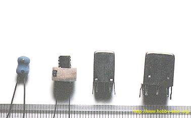 The photograph shows an example of a small coil component. The photograph shows an example of a small coil component.The component on the left is wound with thin copper wire to a small barbell-shaped ferrite core, and has a value of 100µH. It is used for high frequency resonance, or for detering of high frequency. As for size, the diameter is about 4 mm, the height about 7 mm. The value of the small coil like this is indicated with a color code, just like a resistor. The strengh of this type of coil varies from 1µH to several hundred µH. 1µH, 2.2µH, 3.3µH, 3.9µH, 4.7µH, 5.6µH, 6.8µH, 8.2µH, 10µH, 15µH, 18µH, 22µH, 27µH, 33µH, 39µH, 46µH, 56µH, 68µH, 82µH, 100µH other. The second coil from the left has thin copper wire wound around a stick-shaped ferrite core. It is used the same as the component above. The value is 470µH. The diameter of the core is 4 mm, height is 10 mm, and the diameter of the coil is 8 mm. The two devices on the right in the photograph are high frequency transformers. They are used for intermediate frequency (455KHz) tuning of transistor radios, or for oscillator circuits. To shield the coils from magnetic flux, and to prevent the coils from interfering with other circuits, the high frequency coils are housed in a metal case called shield case. This case must be connected to ground. As for tuning or oscillation, this type of transformer can change its value of inductance. Adjustment of the Inductance Value 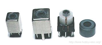 The ferrite core of the coil is made like a screw. The core can be made to move in or out of the coil by turning it with a screwdriver. A special plastic screwdriver is better to use for adjustment of the coils. By moving the ferrite core in or out of the coil, the value of the coil's inductance can be changed. The value of inductance can also be changed by changing the number of turns of wire that comprise the coil, but in fact it is not possible in any practical way. You want try it ? The tuner of an FM radio handles very high frequencies (about 70MHz to 100MHz). The coils used in the tuning circuit are hollow; i.e. they have no ferrite core. A coil with a ferrite core has too much inductance too be used in such a circuit. To adjust the inductance value of a hollow coil, the spacing between the loops of the coil is changed. When you disassemble an FM radio, you may find these coils to appear a bit untidy. Do not try to "fix" the coil by making it a perfect set of loops. The coil has been bent intentionally, in order to be adjusted precisely. 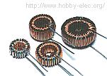 The toroidal coil consists of copper wire wrapped around a cylindrical core. It is possible to make it so that the magnetic flux which occurs within the coil doesn't leak out, the coil efficiency is good, and that the magnetic flux has little influence on other components.  |