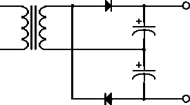
Figure 4.10: Voltage doubler circuit.
A voltage multiplier circuit is shown in figure 4.10. We can think of it as two half-wave rectifier circuits in series. During the positive half-cycle one of the diodes conducts and charges a capacitor. During the negative half-cycle the other diode conducts negatively to charge the other capacitor. The voltage across the combination is therefore equal to twice the peak voltage. In this type of circuit we have to assume that the load does not draw a significant charge from the capacitors.

Figure 4.10: Voltage doubler circuit.