SECTION 3 Putting it together
Chapter 10
We need a box and a sensor. The sensor needs to be made useful for the bike application. Let's discuss the sensor first.
To make the simple bike computer into a useful article, we need to roll up our sleeves yet once again and prepare to put it onto a real life bike.
The PCB we have made is big and has plenty of space for cutting and adding other bits and pieces. But if we want the final satisfaction of seeing it working, mounting the lot on a real bike, it is a bit too big.
Way back in chapter one, we discussed sensors and I recommended we should stay with the herd and use some sort of hall device. Well now we physically need one to get our hands on.
I realise that it is almost impossible to buy a potted sensor +cable as a spare, they all come with a bike computer. Now we could buy a complete bike computer kit and throw the computer away. Or keep it for later as a spare.....
The other way is find an old bike, or in your electronic junk shop, or junk box... But somehow we have to obtain a sensor and a cable.
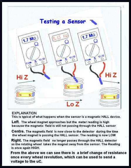 Fig.31 Really basic sensor diagram
So we have results similar to the diagram. Similar means there is a measurable resistance change when the magnet is passed over and CLOSE to, he sensor body.
Now back in chapter one we also mentioned it was possible we would need to get a power supply to certain types of sensor.
Let's suppose we have found a sensor in a junk box. We need to know if it is a coil device or a Hall device.
What is the difference for our project?
Well the coil device generates a
voltage every time the wheel magnet passes by so it needs NO voltage to make it work.
How can we check? I connected my multimeter on the mA scale across the end of the sensor wire in the handle bar mount shoe ( place where it enters the computer).
The reading is of course zero mA. Next I took one of those little kitchen fridge magnets and waved it very close ( 1mm) to the “Unknown type” of sensor. I had to find the best direction to move the magnet over the sensor, but eventually I got a reading of a about 50 uA
Well I cheated as I knew it was a coil sensor, but if it hadn't been a coil sensor, instead some sort of HALL device, then we would have no change at all when the magnet was passed across the sensor body.
Just for the sake of argument, the one you found gives a pulse of current or volts when you pass the magnet across it, then what?
In that case we would need to condition the pulse output. For those interested, basically a limiting amplifier to ensure that even at the slowest speeds there is enough signal for the PIC to detect at the PORTB input. But this could be tricky, without an oscilloscope, so unless you really have set your heart on making it work, best look for a HALL device type sensor.
OK let's suppose we have found a HALL device, it is easy to test?
No panic about getting a voltage supply, lets look at the following drawing on how to test a HALL type sensor. The voltmeter on the ohms range will normally give you the required voltage-...
The way I tell it ( my apologies to the late great Edwin Hall )
As we all know, the apple was discovered thanks to Sir Isaac Newton , but who discovered the Hall effect?
Once upon a time a man was playing about with, frogs legs , batteries etc , passing current through his solid iron (apparently Aluminium was too expensive in those days) breakfast tray. He simply clipped the battery across the ends and his DVM across the sides.
He tried a lot of things to measure the voltage , but to no avail. However one day he was messing about with magnets trying to lift the iron tray when he noticed that the voltmeter which had been left by accident from the previous session, was reading a voltage!!
He jumped up and shouted Eureka, ( was that someone else? ), I will call this the quantum charge displacement effect. However the cleaning lady was becoming frustrated as all this was stopping her getting on with things
She said, why not try out your charge thingie again in the Hall sir?
Annie it 's called the …. Annie was firm…. Hall sir
Yes Annie, Hall is a good idea.
Well he pottered about for a couple of days testing the magnets position and the amount of current.
He got best results with something like this….. a very small millivolt reading.
The modern version comes with built in amplifiers and protection.
The drawing shows what happens as we pass the magnet across a HALL sensor. In my case I had one that gave a change of reading from megohms to kiloohms. A range of 1000 to 1.
So let's test yours. Don't forget to select the OHMS function on your meter. The range is adjusted for best results. This depends on the device you have found/bought.
Caution. The battery here is inside the DVM, and is current limited. The hall device doesn't care really which way you apply the battery vpltage but the amplifiers and circuits for conditioning do.
Fig.32 Bikehall 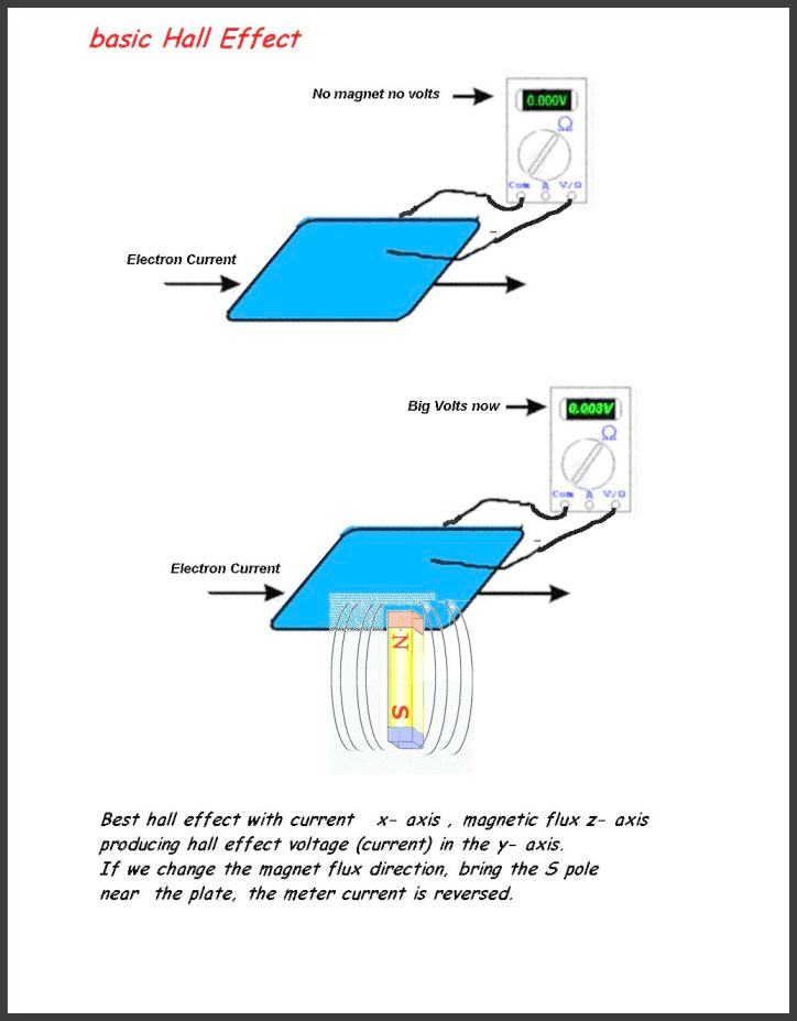
If we are lucky the device will only give a reading from the magnet when connected one way, the other nothing .
Other sensors will read with the DVM ( as battery) both ways ( depends on the internal circuitry). Here the correct battery polarity is when there the reading with magnet is much larger than the reading without.
Using the ohms reading:- away from the magnet is HIGH ohms,
magnet present is LOW ohms, the reverse of the volts readings .
Once we use a real battery we will provide an input protection for the sensor, limiting the maximum current.
Looking at the snippet of our theoretical circuit we have a large resistor, 100k between the 5V battery and the sensor. Even if the sensor becomes a dead short wrong way round, the maximum current is 50uA, so this class of device is protected from .damage. Also note that the battery in the Bike computer box is also protected from external short circuits.
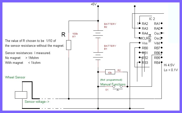
Fig33 Modification to circuit for Hall sensor
The i/p to RB4 is either effectively 0V or 4.5V,
Both values are correct CMOS levels for the PORTB input RB4.
Notice we have inverted the logic :-
Hi I= no magnet pulse, Lo = magnet pulse.
We have to change the source code to accommodate this, or pass the HALL sensor voltage through an inverting transistor before applying to RB4. ( the code change is less bother).
The above may not work if the sensor we have found is not meant for a bike wheel.
For a bike wheel?
Yes, we don't want to measure the flux strength, we only want to measure if there is flux or if there isn't. Something that detects that sort of situation is a simple magnetic switch .
Are there other types?
Yes, there are linear detectors aimed at flux measurement. These are much more complex and require more care in use.
There are many bike types. But the type we are using belongs to the first group , the simpler on off switch. Let's look at the history biefly again
The metal plate used in the beginning was replaced later by semi-conductor materials which gave a much larger Hall current. Looking at it another way, the original device required a lot of current , amps to get a hall output, microamps. The modern device has reduced this two milli amps. For a bike this is still a lot of current drain for the battery, and switching sampling, duty cycle operation schemes are employed to keep the current down.
So, if we talk about milli amps, our drawing resisto R = 100k r will have to be scaled to allow more current to pass. ( otherwise the device will not be able to function).
A lower limit however is needed. If with 1 K for R there is no change, then something else is wrong. Either the sensor is dead, or we have found the original HALL tray. For a bike, no good. Look for another.
The Bike mounted PCB
The pcb is too big for mounting on the bike so we have to reduce it in size.
We do two things.
- Chop out all the bits not strictly necessary, e.g. the voltage stabiliser circuit.
- Reduce the size of what is left.
The latter at first sight is the most complex, but no it isn't. Lets compare the circuits to see how it is almost done for us. The PCB at the bottom has everything, while that on the
top
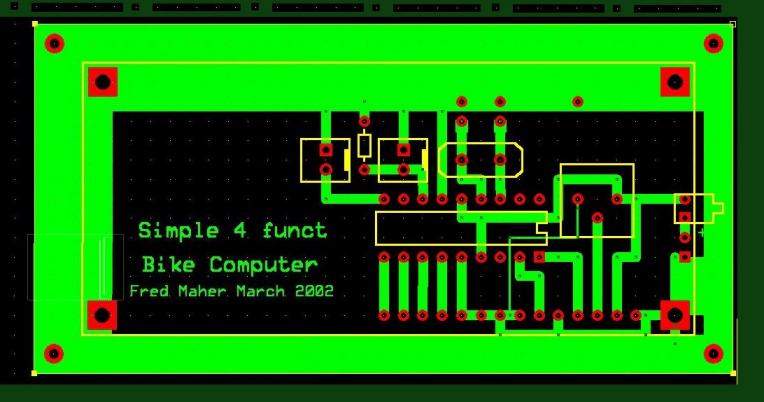
Fig 35. Bare bones PCB for simple
bike computer
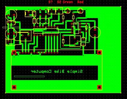
Fig 36 complete PCB simp bike +"development " components
has been pruned to the bare bones necessary for the bike. We can see where
the timer and power supply bits have been eliminated, and the board is very much smaller. What else has been done?
Well the key is the LCD.
It is now mounted over the pcb tracks. Fig35 Simple Bike PCB
The other components are mounted as before on the non PCB copper side. Does this mean we now need a PCB with tracks top and bottom'? No, because we use the original connections.
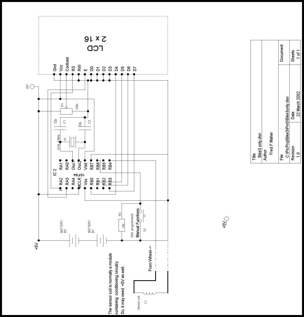
Bike only Theoretical diagram
The theoretical circuit diagram is shown below. By bike only, we mean that all the extra components for testing have been removed. Also above ,the important interface component for the sensor, R, has had a large discussion on how to connect different types of sensor to the Simple Bike Computer.
Fig.37 Simple bike computer ( no development components)

This tries to be a general circuit for any type of sensor.
Earlier in fig35 we have shown and discussed, the varable factors and some ways to adapt a HALL sensor to the microcontroller PORTB.
We hope we have covered the topic in sufficient depth for the reader to be aware of the different types of sensors and so to be able to adapt his sensor to the PIC.
The Box
We are now ready to put it all into a box, but first lets look at the lid diagram below.
This is the most complex mechanical part.
The lower side view is of course will be the component side. I have tried to combine various photos to see how the lid will look spread out.
Please note that the top of the lid will have the LCD inside and only the Display and the silver coloured bezel visible.
Let's try to see how the components and the LCD have been realigned.
Visualize sliding the LCD module , round and down onto the pcb side. .The connecting pins are unmoved. BUT, we have now covered the lowerside tracks and the lid top diagram can only show the mounting holes and the LCD module .
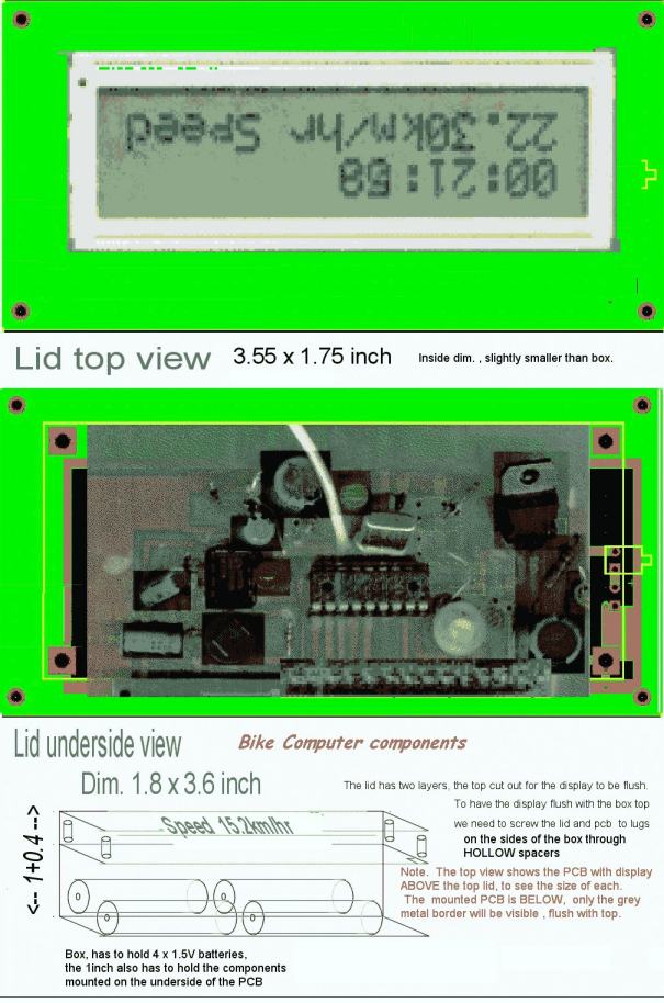
Fig 38 The box lid with PCB
The lower diagram, Lid underside view shows the components. The blackened areas are components only used on the complete version. We have blacked out the timer and the power supply stabilizer..
The bottom portion of fig38 lid drawing, shows th rest of the box.
The height is about 1.4 inches. The top 0.4 inch is taken up by the Display and LID as well as the underside components.
The remaining 1 inch below houses four AA size 1.5V batteries. . The conection to the sensor is best made detachable, say with a 3.5mm audio phone jack and socket. Mount the socket on the side of the box. Tthe battery on/off switch will be mounted on the side as well..
There should be sufficient space for the box to be mounted on the handlebar in the space between the brakes and gear changes.
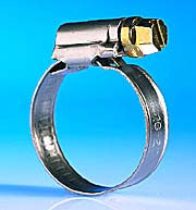 The box itself can be secured to the handlebar by many means. I personally use
Plastic ties, but a jubilee clip is also a good choice. See fig 39
Fig39 25mm Jubilee clip
The appendix that follows holds the up dated PCBs