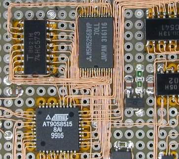
 To build any circuit, some wiring has to be done. Most people
are wiring circuit boards with PTFE (Teflon) insulate wire. But PTFE is
inefficient.
re-translated (correctly, I think) from http://elm-chan.org/docs/wire/wiring_e.html
 To build any circuit, some wiring has to be done. Most people
are wiring circuit boards with PTFE (Teflon) insulate wire. But PTFE is
inefficient.
I recommend using UEW for protoboard. The UEW is polyurethane coated copper wire which is used in inductors and small transformers. You might think that wiring a board with such a small wire would be difficult, but I have solved most of these problems.
To wire with UEW, a wiring tool called a "wiring pen" is used. The wiring pen is often sold with PCB kits, however, they are not useful because its tip is dull. If you haven't already paid for one, it will be better to build it yourself. I built the wiring pen from a mechanical pencil with paper clip spool holder and a small sewing thread spool.
I have found, 0.2 mm dia (32AWG) UEW is the best for wiring the PCB. This is equivalent to 0.9 mm print pattern. Its insulation is sufficient for low voltage circuits (below 20 volts) such as a logic board.
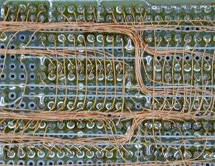 It
is very easy to wire in high density layout, even if parts are mounted on
the board without free space.
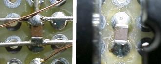
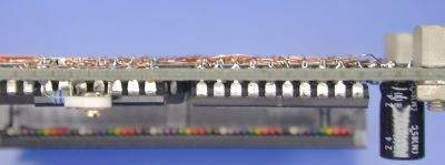 Left image shows the solder surface. It is very neat because the insulation
coat of the UEW is very thin.
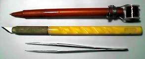 This
is a wiring pen that I built along with tweezers and an exacto knife. I wind
the UEW to a bobbin and set it in the tail of the wiring pen, then wire like
I am drawing a line.
When I first learned to wire, it was with wire-wrap by Vector slit 'n wrap with thin PTFE which wasn't too bad when the circuit had a lot of daisy chains and big wire wrap sockets. To wire in point-to-point like wiring with PTFE wire is better for them. However, it is not suitable for wiring random logic, analog circuit and surface mounted devices because of all the end points which must be stripped and soldered. Now I am working in this new UEW method. The polyurethane coat at the end of the wire burns away in heat so that pre-soldering to the UEW without any stripping process is very possibly. A 350°C tip temperature is recommended for UEW.
When I am using only through holed protoboard, I cut the leads at solder surface to zero height, so I can wire smoothly and to prevent damage to the polyurethane coat by the sharp edge of the leads.
 How
to mount SMD
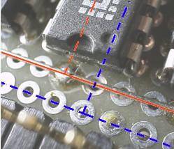
To mount SOP or QFP devices, most will use pitch conversion boards. However the conversion board is expensive and requires mounting area, it is not a neat method. I just mount the SMT devices on the protoboard directly.
To mount the SMDs without pitch conversion board, put a polyimide (Kapton) tape on the board to insulate, bond the device to the tape and solder wires directly to each lead. The polyimide is heat resistant material which is used for high temperature insulator, film cable and PCB. It can work up to 200°C continuous and is unaffected by the soldering temperature. To solder a wire to a lead, simply pre-solder both, then press the wire to the lead with the soldering iron; very easy.
Questions:
James Newton replies: Also look for Magnet Wire or wire with a Poly Enamel jacket. Mouser has these: http://www.mouser.com/Search/Refine.aspx?FS=TRUE&Ne=688785&N=254620+4294656337+4294654451+1323038&Ns=P_SField+
| file: /Techref/pcbwires.htm, 5KB, , updated: 2015/7/14 14:18, local time: 2025/10/11 10:15,
216.73.216.53,10-2-207-162:LOG IN
|
| ©2025 These pages are served without commercial sponsorship. (No popup ads, etc...).Bandwidth abuse increases hosting cost forcing sponsorship or shutdown. This server aggressively defends against automated copying for any reason including offline viewing, duplication, etc... Please respect this requirement and DO NOT RIP THIS SITE. Questions? <A HREF="http://techref.massmind.org/techref/pcbwires.htm"> PCB Wirings</A> |
| Did you find what you needed? |
Welcome to massmind.org! |
|
Ashley Roll has put together a really nice little unit here. Leave off the MAX232 and keep these handy for the few times you need true RS232! |
.