
Yes, I know I skipped September, it is still in the works but having digital
camera issues. I can't seem to get good closeups. Does anyone know how to
adapt a macro lens to an HP Photosmart 435?
Position
Finding your position seems to have only one answer these days: GPS. And
it is excellent. New systems are becomming available to increase the resolution
of a reciever within a limited area. For example, one research group was
able to control the position of a small "car" to within a few centimeters
inside a large building. This is done by adding "pseudolites" which act as
local area positioning beacons for the GPS system. Also, GPS recievers continue
to decrease in size and price. It will not be long before linear encoders
will be replaced with GPS units!
David Beals [DBeals at transdyn,com] has sent along some very nice SX code
to read a GPS unit and display the info on an LCD.
Optical Encoders
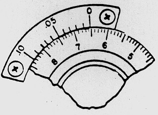 One of the
things that pushes up the price of encoders is the need for fine resolution
and the tiny sensors and disks that this implies. There is a way to use larger
components and achieve fine resolution. I'm not exactly sure why it isn't
used more, but I think the reason is that, although it is very accurate and
fine in the long run, it does not produce a perfect position signal for each
"click." The idea is to use a "vernear" arrangement of sensors just like
the marks on a vernier caliper as invented by
Pierre
Vernier in 1631. What! You don't know what that is?
-
Vernier Caliper:
-
"An instrument for accurately measuring length. It has two graduated scales,
a main scale like a ruler and a second scale, the vernier, that slides
parallel to the main scale and enables readings to be made to a fraction
of a division on the main scale."
simulations: HTML
Java
Now, it turns out that this vernier trick accounts for some of our visual
abilities:
Here is a little JScript simulation of an optical encoder using vernier techniques. Note: This only works in IE, not Chrome, etc... Notice that the Mask and Source holes are quite large compaired to the
resolutions of the pulses given on the graph. If you aren't viewing this in Internet Explorer v 5.5 or better, you are probably not seeing the animation. It uses
a groundbreaking (I believe) technique which takes advantage of the content editing engine, DHTML, and JScript. This method and this code is GPL so feel free to use it
and improve it. But always include a reference back to this web page.

Absolute Position Encoders
The more standard
position recovery sensors are Absolute Position Encoders:

This type of encoder also uses several sensors, but each sensor follows its
own track, reading one ring of the encoder disk. Each ring is printed with an
encoding of a single binary digit; the LSB on the outside track and the MSB on
the innermost track. This order takes advantage of the increased space towards
the edge. By reading all the sensors, the rotational position of the disk can
be known as a binary value, to the limit of resolution dictated by the width
of the marks on the LSB track.
This disadvantages of this system are that it requires more sensors and so more
IO pins, its accuracy is limited by the width of the LSB track, and it must be
large enough to separate each track / sensor.
The advantage is, of course, absolute position sensing, which means it can be
used with a very slow processor, as there is no worry about missing a pulse.
Psuedo random pattern encoders
This type of encoder has the unique property of letting you determine the
absolute position (within the entire range) with less than the expected minimum
number of bits required for complete absolute resolution. It does this at
the expensive of you needing to actually move the encoder several steps in
order to "see" the pattern in the changing bits. When enough steps in the
encoder position has passed by, the resultant pattern then is unique to one
and only one spot within the full combination of the code. In essence, after
a minimum number of increments, the absolute position can then be easily
determined.
The deal is that you need a cyclic (repeating) code sequence N bits long
in which any given string of M bits is unique. You then draw this sequence
around your code disk, and you need to move only M bit positions to read
M bits of code at startup; you then know where you are in the whole N-bit
sequence.
The figure shows, as an example, a 31-bit term Psuedo Random Binary Sequence:
0, 0, 0, 0, 1, 0, 1, 0, 1, 1, 1, 0, 1, 1, 0, 0, 0, 1, 1, 1, 1, 1, 0, 0, 1,
1, 0,1, 0, 0, 1, generated by a 5-bit shift register. If you imagine a window,
5 bits wide, which can be pieced together by reading 5 bits in turn with
a single photocell with another photocell following a standard linear pattern
which acts as a "clock", each window position is unique and tells your position
to within 1 bit.

 Now, it's
obvious that the best you can possibly do is N=2^M, because by reading M
bits you only have 2^M possible values. It may be that there are some codes
that have this property. On the other hand it is very easy to find codes
that do nearly as well, giving N=(2^M)-1. These are the "pseudo-random binary
sequences" which can be generated using linear-feedback shift registers.
There's a useful section on these in Horowitz and Hill, and no doubt many
other places. The good news is that the idea is basically sound. Suppose
M=10, then you can do a 1023-position encoder and get absolute position after
moving only 10 positions, i.e. about four degrees. A lot better than forcing
your milling machine, industrial robot or whatever all the way back to its
"home" position on every startup. I think that the most useful application
would be for long linear tracks such as would be found on gantry robots powered
by linear motors.
The bad news is that the pattern you must print on the code disk is no longer
simply periodic, and it is therefore impossible (I think - certainly very
tricky) to use Moire or vernier techniques to get high resolution
with only one encoder. So this might be something you would add to an existing
low resolution absolute position encoder: Basically, two low res encoders,
in a vernier arrangement, can produce a VERY high resolution encoder, with
absolute position readout after a few steps.
The other problem is that finding a sequence in a list of 1023 bits will
be slow at best. If you know a fast way to manage this, please let me in
on it?
Index hole multiplication
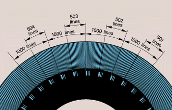 I remember
a Heidenhain rotary encoder with a 'normal' incremental code. As an extra
feature it had multiple (32?) index holes. The distance between these index
holes was not equal and therefore you could retrieve the absolute position
by counting the number of encoder pulses between two index hole pulses.
Sort of like pulse width modulation.
In order to be useful, the lines have to be very thin. Otherwise you can't
count high enough between two index holes to provide for a unique identification
of the index holes or you can't have enough index holes to make it worth
doing. Here is a perfect opportunity for vernier encoding to help reduce
the cost of the system by allowing lower resolution sensors to count the
lines.
See also:
-
http://iwant2study.org/lookangejss/01_measurement/ejss_model_AAPTVernierCaliper/AAPTVernierCaliper_Simulation.xhtml And HTML5 Verier Caliper simulator.
Drag the slide and sample object from the exact points shown to measure the sample, then enter your measurement at the top and press enter to see if you are right.
-
http://www.phy.ntnu.edu.tw/java/ruler/vernier.html
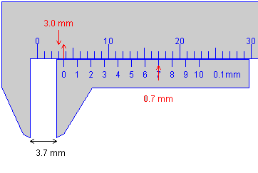
An excellent little Java Applett that shows how to read a Caliper. Here is
a sample of it showing a reading of 3.7mm
-
http://www.heidenhain.com/phaise2/posps.html
When a scale with a line grating is moved relative to another grating with
the same structure - the scanning reticle - the lines of two graduations
alternately align. The resulting light-dark modulation is sensed by photovoltaic
cells.
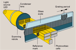
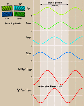
The index grating with one scanning field of two interlaced phase gratings
generates four images on the measuring standard, with each image phase shifted
by one-quarter of the grating period. Since only one scanning field is used
to generate all four scanning signals, fluctuations in the intensity of the
light such as are caused, for example, by local contamination of the scale,
have an equal effect on the four photocell signals. The sinusoidal output
signals therefore retain a high quality even with a certain degree of
contamination.
-
https://www.youtube.com/watch?v=0QLZCfqUeg4
Using a linear position encoder strip from a printer with the arduino.+
-
http://www.geology.smu.edu/~dpa-www/robo/Encoder/pitt_html/encoders.html
-
https://hackaday.com/2018/03/07/0-05-mm-precision-thats-a-moire/
A parametric 3D printable caliper using moire interference.
-
http://www.site.uottawa.ca/~petriu/PositionRecovery.pdf
Sensors and Measurement Techniques for Position Recovery and Object Localization.
Pseudo-Random Encoding. Includes a section on "3D Object Recognition Using
Structured Light"
-
http://www.gurley.com/Virtual_Absolute.pdf
Commercially available Pseudorandom encoders. Very good summary of best
application cases.
-
http://openjscad.com/#https://gist.githubusercontent.com/JamesNewton/c8598878736442c440bbe41d086291ac/raw//encoderdisk.jscad
A parametric quadrature optical encoder for laser cutting. (change Output to "Parts" and select DXF or SVG Generation).
-
https://github.com/HaddingtonDynamics/Dexter/wiki/Encoders
Analog optical readings of sensors 90' out of phase form a circle when plotted.
Each circle results from the motion of a single slit. With a 12 bit A2D, there
are 4096 possible values from full dark to full light, then another 4096 back
to full dark, so 8192 values per slit. With up to 200 slots per disk, that gives
more than 1 MILLION positions per revolution.
file: /Techref/new/letter/news0312.htm, 22KB, , updated: 2018/11/16 15:03, local time: 2025/10/11 19:07,
216.73.216.53,10-2-207-162:LOG IN
|
| | ©2025 These pages are served without commercial sponsorship. (No popup ads, etc...).Bandwidth abuse increases hosting cost forcing sponsorship or shutdown. This server aggressively defends against automated copying for any reason including offline viewing, duplication, etc... Please respect this requirement and DO NOT RIP THIS SITE. Questions?
<A HREF="http://techref.massmind.org/techref/new/letter/news0312.htm"> December 2003 MassMind newsletter</A> |
| Did you find what you needed?
|
.
 One of the
things that pushes up the price of encoders is the need for fine resolution
and the tiny sensors and disks that this implies. There is a way to use larger
components and achieve fine resolution. I'm not exactly sure why it isn't
used more, but I think the reason is that, although it is very accurate and
fine in the long run, it does not produce a perfect position signal for each
"click." The idea is to use a "vernear" arrangement of sensors just like
the marks on a vernier caliper as invented by
Pierre
Vernier in 1631. What! You don't know what that is?


 Now, it's
obvious that the best you can possibly do is N=2^M, because by reading M
bits you only have 2^M possible values. It may be that there are some codes
that have this property. On the other hand it is very easy to find codes
that do nearly as well, giving N=(2^M)-1. These are the "pseudo-random binary
sequences" which can be generated using linear-feedback shift registers.
There's a useful section on these in Horowitz and Hill, and no doubt many
other places. The good news is that the idea is basically sound. Suppose
M=10, then you can do a 1023-position encoder and get absolute position after
moving only 10 positions, i.e. about four degrees. A lot better than forcing
your milling machine, industrial robot or whatever all the way back to its
"home" position on every startup. I think that the most useful application
would be for long linear tracks such as would be found on gantry robots powered
by linear motors.
 I remember
a Heidenhain rotary encoder with a 'normal' incremental code. As an extra
feature it had multiple (32?) index holes. The distance between these index
holes was not equal and therefore you could retrieve the absolute position
by counting the number of encoder pulses between two index hole pulses.

