The Manson Engine-Builder's Notebook
The Manson cycle engine was designed back in
1952 by A.D. Manson and first published in Newnes Practical Mechanics
March 1952 p193.
Click here for
page 1
of the article
650k
Click here for
page
2 of the article
245k
Contains constructional notes and drawings of the original Manson engine.
Caution these are big files! If you prefer to read off the screen,
this text now fully transcribed - scroll down to view text and
diagrams.
For a 38k downloadable Word file describing the cycle, some variations and some recent work- click here.
So how does it work,
and what can it do for me?
The Manson cycle is one of several
thermo-dynamic engine cycles which uses the thermal expansion of air to do
work. When air is heated it expands and this expansion can be used to make
a piston move out in a cylinder. Then the air is cooled and the piston will
move back.
When the piston is coupled to a crankshaft and flywheel it will do rotary
mechanical work and this can be used for turning machinery, pumping water
or generating electricity.
The key feature of the Manson is that it uses external combustion and therefore
can use any fuel which can be burnt. It could also be made to run using the
heat of focussed sunlight.
One of the novel features of the Manson engine
is that it only requires one moving part to do useful work. Other engines
like the Steam or Stirling engine rely on separately moving valves
or displacers to control the cycle, and this adds to engine complexity. The
Manson, I believe, is thus unique, and this is the attraction - a simple
heat engine with minimum moving parts.
The engine works on the principle of 2 power strokes, firstly an expansion
stroke which pushes the piston outwards when the internal pressure within
the engine exceeds the external (usually atmospheric) pressure. This
expansion stroke is then followed by a vacuum or suction stroke. At the end
of each stroke a port is opened to the atmosphere, by the piston skirt, and
thus the internal pressure of the engine is restored to atmospheric pressure
so that the cycle may begin again.
Key Technical Points
The displacer in the Manson engine is connected directly to the power piston.
This power piston needs to be of a given diameter with respect to the displacer
in order to get the most work from the expanding air. If the piston
diameter is too small then it will see very little force, if it is too large
a diameter, then it will occupy too much volume in the cold end leaving very
little air left in the remaining annular gap to displace to the hot end and
expand. Obviously there must be some optimum ratio between displacer
diameter and piston diameter.
Using Steve Truscott's Manson Calculator this can be shown to be a piston
diameter of 46% of the displacer diameter.
The annular gap between displacer and Hot cap should be about 1/32" (0.8mm)
for every inch (25mm) of diameter.
Scaling up from Manson's original sketch (Fig. 1 ) he seems to have got these
figures fairly correct!
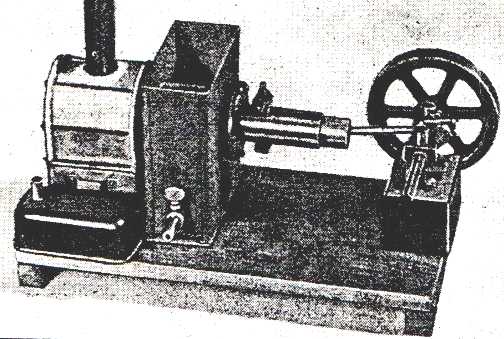
Figure 1 shows the first Manson Engine as published
in Newnes Practical Mechanics.
The spirit burner on the left, heats up the hot cap, whilst the right hand
side of the engine is kept cool with a water jacket. A heat break of asbestos
washers and the firebox wall helps to isolate the hot end of the engine from
the cold end.
With the engine in the position shown, top dead centre (TDC) , the air inlet
port has just opened and the air from the outside rushes in to equalise the
pressure inside the engine with atmospheric pressure. The flywheel inertia
carries the engine past TDC and the air inlet port closes.
The piston and displacer now begins to move outwards to the right and the
relatively cold air in the cylinder marked A is displaced to the hot
end. It is squeezed down the annular gap between the displacer and hot cap
and heats up rapidly. It begins to expand and the internal pressure of the
engine starts to rise. above atmospheric pressure. As a result the heated
air exerts pressure on the piston and it is accelerated to the right thus
performing the expansion stroke.
On reaching the end of the stroke, the pipe C running down the centre of
the engine, now lines up with the exhaust port X on the cylinder wall. Any
remaining internal pressure is vented to the atmosphere as the heated air
rushes down the exhaust pipe.
The internal pressure of the engine is now restored to atmospheric pressure
as the exhaust port closes. The flywheel carries th piston past BDC and the
piston displacer combination begins to move inwards to the left.
There will still be some residual hot air in the hot end, but as the displacer
returns, this is displaced to the cold end where it cools and contracts and
the pressure rapidly falls below atmospheric pressure. The pressure of the
atmospher outside, now pushes the piston to the left performing the vacuum
or suction power stroke, untill all the internal air is at the cold end.
The air inlet opens and the engine cycle continues.
The pipe C, running down the centre of the displacer was a means of conveying
the hot exhaust air down through the middle of the engine without causing
it to heat up the cold end of the engine.
The pre-heated air coming from the exhaust could be used to provide additional
hot draught to the fire - particularly if solid fuel was being used.
So to Sum up the Manson Engine.
It is an open cycle external combustion
hot-air engine, with the cycle controlled by a piston operated valve.
The displacer and piston move together as a single component.
There is an expansive power stroke and a power suction stroke making two
power strokes per cycle.
The engine, when started will run in either direction.
The piston diameter should be 46% of the diameter of the displacer.
The engine is of simple construction and may be very attractive to Developing
World production where only a few tens of watts are required. It can be made
easily on a lathe and drilling machine using common materials.
 |
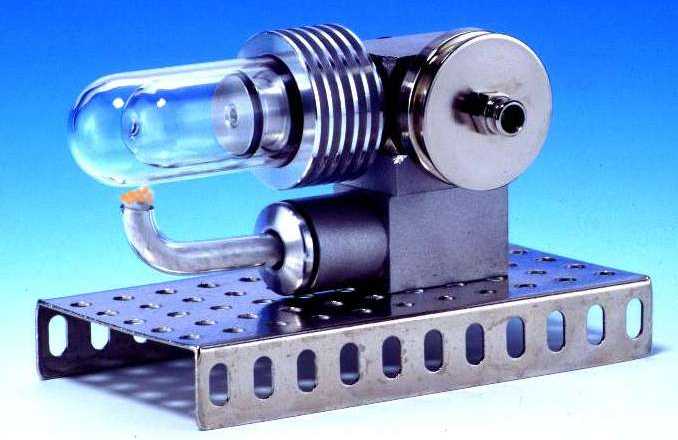
Here is a Rupp-Heis-Luft-Moteur by E.Schmidt of
Germany. It's a type of Manson Engine, modelled expertly in pyrex and ground
glass. This engine can be bought from
E.
Schmidt's website with many types of
Stirling engine. You can also write to :
PBO. 2006, Koernerstr. 3, D-61440 Oberursel, Germany. The cost
is DM 327 -about $150.

|
Email Ken to discuss Manson Engines
 |
Working
Cylinder.
This cylinder is made from a piece of mild steel pipe, the finished size
being 1/1/8 " bore (28.5mm) by 3.125" (79.5mm) long.The outside
should be turned bright and the step to receive the flange should be cut
for a distance of 3/16" (4.75mm) at one end. Before smoothing
out the bore the air-inlet ports and the exhaust port should be drilled,
care being taken to ensure their correct positions.
The cylinder flange is made from a piece of mild steel plate 3/16" (4.75mm)
thick. It should be turned and a spigot of 1/32" (0.8mm) made on the inside
to fit the mouth of this displacer chamber. A light groove should be cut
on the otherside to mark the position of the 8 fixing screws, the holes for
which should now be drilled. The flange can now be used as a jig to drill
the tapping holes in the chamber flange ring. The flange can now be pressed
or lightly driven onto the cylinder and solder should afterwards be
applied all around the joint. A thick paper gasket rubbed with oil and graphite
will make an airtight joint when the cylinder and chamber are finally united
together.
The
Displacer.
The displacer can be made from a piece of tube or from sheet metal abou 1/32"
thick . The outside diameter should be 1/16" (1.6mm) less than the inside
diameter of the chamber. One end is dished like that of the chamber whilst
the other end is about 1/8" (3.2mm) thick and flat. All joints on this part
should be brazed or welded and airtight. A hole should be bored in eache
end at its centre to thake the 1/4" (6.35mm) bore exhaust pipe C.
The
Piston.
the piston which is in the form of a tube can be brass or other anti-friction
metal. It should be 4.5" (114.3mm) by 1.125" (28.5mm) outside diameter
and a fairly tight fit in the cylinder. A flange 3/16" (4.75mm) thick having
four equally pitched , countersunk holes for the 1/8" screws (3.5mm)
which unite it to the displacer , is fitted at one end. It can be brazed
or soldered to the piston and afterwards this part should be trued in the
lathe and the outside diameter of the flange made equal to that of the
displacer.
There is also a disc soldered in the piston tube flush with the flange
at this end. It is about 1/8" (3.2mm) thick and it is bored at its centre
to take that part of the exhaust pipe which is fitted inside the piston.
The air inlet pipe should then be made and fitted, care is necessary to fit
them in their correct positions. See Fig. 1.
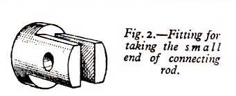
A short piece of brass rod (Fig.2 ) having a slot
cut to take the small end of the connecting rod has also to be fitted and
soldered inside the piston. The hole for the gudgeon pin is then drilled
square through the piston tube and the pice of brass which thus forms the
bearing for the gudgeon pin. The gudgeon pin is held in position by a short
screw passing through the upperside of the top end of the connecting
rod and for a short distance into the pin itself. A hole in the piston tube
allows the pin to be fitted.
Having got the piston to this stage it should now be made a good sliding
fit inside the cylinder by lapping, using metal polish as a grinding
medium.
Two or three asbestos washers are fitted between the piston flange and the
displacer to prevent as far as possible, heat getting to the cold end. Bt
varying the number of the above mentioned washers, the length of the displacer
can be finally adjusted.
When assembled the piston should move freely the full stroke of the engine,
and allowing 1/16" (1.6mm) for clearance the displacer should not rub on
the inside of the displacer cylinder.
The exhaust should be on the top and the air inlet on the underside of the
cylinder. The connecting rod does not need to be heavy. A disc or a double
web crank can be used. The crankshaft may be 5/16" (8mm) diameter and the
flywheel about 5" (127mm) in diameter.
Cooling Water
Tank.
This tank can be constructed of galvanised iron. It will have to be soldered
to the displacer chamber, and the bottom, which should be 1/16" (1.6mm) thick,
will have to project 1/2" (12.7mm) at each side to take the holding down
screws as the thrust and pull of the piston is taken on this part.
A Novel Hot Air Engine;
Constructional Details of an Experimental Double Acting Model by A.D.
Manson.
From Newnes Practical Mechanics 1952.
The hot air engine here described works on a new
principle devised by the writer. As will be seen by the sketch (Fig. 1.)
it is simple and therefore should not be difficult for the average mechanic
to construct.
The illustration shows the piston, which is tubular, to be directly
connected to the displacer so that they move together as one piece.
The working cycle is as follows: starting on the out stroke. As the piston
moves out the cold air contained in the cold portion of the displacer
chamber A, is displaced to the hot end and the pressure gradually rises,
so driving the piston. At the end of the outstroke the piston comes
to a position where the two ports X register, and therefore all the air above
atmospheric pressureescapes from the hot end. On the return stroke the small
quantity of hot air remaining in the hot enf of the displacer chamber is
displaced to the cold end and cooled, therefore, a partial vacuum is formed,
which increases as the stroke continues and the piston is thus forced in
by the pressure of the atmospher until near the end of the stroke, when the
air inlet port registers with that of the working cylinder. Air now rushes
in to fill the vacuum and the cycle of operations is thus completed.
The following are the advantages of this type of hot-air engine:
The heated air during the out stroke remains in the hot end until the end
of the stroke and is discharged directly from the hot end to the atmosphere
and thus heating of the cold end is avoided to some extent. The incoming
air is always at atmospheric temperatuer and pressure.
The engine is double acting and can be reversed. There are few moving parts,
no additional mechanism being required to drive the displacer.
Constructional
Details.
Starting with the displacer chamber, this is made from a piece of mild steel
tube, or it can be constructed from a piece of sheet metal not more than
1/32" (0.8mm) thick. One end is closed by a piece which is cut a little
larger than the diameter of the cylinder. It is then beaten out hollow or
dished, as in Fig 1. and fitted in the end of the tube, being secured air
tight by brazing or welding.
A ring made from 1/4" square iron rod, or cut from plate, is fitted on the
outside of the other end. It can be brazed on or soft-soldered. The chamber
should then be placed in the lathe and the ring trued up as it has to carry
the working cylinder.
 |
 |
 |
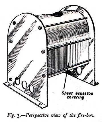
The firebox (Fig. 3.) is made of 1/32" (0.8mm) galvanised iron. Long
studs pass through the ends and hold the centre part , which carries the
funnel in place. It can be lined inside the ends and the centre part covered
with asbestos sheet to conserve the heat.
Three air holes 1/2" (12.7mm) in diameter are drilled on each side at the
bottom of the ends of the firebox. A small fire door is fitted at one side
to allow the lamp to be removed and to prevent too much cold air entering
here.
 |
 |
An XL Spreadsheet to calculate Manson engine design parameters by Steve Truscott.
Digging Deeper
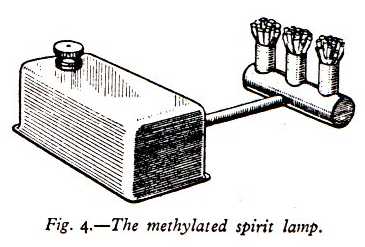
The lamp for burning methylated spirit is provided
with a rectangular reservoir, having a short length of 1/4" (6.35mm) tubing
soldered at the bottom, on the other end of which is another piece
of tubing fitted with three 3/8" (10mm) diameter burners. (Fig. 4).
The wicks are made of asbestos cord twisted together. The lamp should be
placed centrally under the hot end of the displacer chamber. The baseboard
may be of oak or other hardwood 1/2" (12.7mm) or 5/8" (16mm) thick. It should
have two end pieces on to prevent warping, as shown in the photograph
of the completed model.
| Here is the original article from 1952,
updated to include metric equivalents wherever possible. Asbestos washers and sheet as mentioned in the article should be replaced with a more modern heat insulation material. Ceramic board and ceramic paper are possibities. Galvanised iron should be treated with care as it emits toxic zinc oxide fumes when heated during welding or brazing. |
 |
Early sketch of Steve Truscott's Manson Showing arrangement of ports
Manson Cycle indcator diagrams - measured from real engine by Steve Truscott. XL Spreadsheet format
Indicator diagram plots from Steve's first Manson engine. XL format.
Manson Engine Builders to
Date
Steve Truscott
- Australia
Julian Wood UK
Geoff Bartlett UK
a 7cc 0.5W engine 1000rpm.
Ken Boak UK 53mm bore 38mm stroke
Experimental Manson Transferator
Engine
Ole Berge USA a large engine similarto Manson engine
E.Schmidt
Germany
Rupp Heisluftmoteur - on sale, see below
Key Dimensions/Cutting List
Displacer
Diameter 2" 50mm
Displacer Length 2" 50mm
Piston Tube length 5.2" 132mm
Piston Tube diameter 1.125" 28mm
Cylinder Length 3.125" 79mm
Cylinder diameter 1.25" 32mm
Cylinder bore 1.125" 28mm
Con-rod length 3.5" 89mm
Flywheel Diameter 4.5" 114mm
Exhaust tube bore 1/4" 6.35mm
Crankshaft diameter 5/16" 8mm
Crankpin diameter 1/4" 6.35mm
Small end diameter 3/16" 5mm
I am currently devising ways of making the Manson engine more powerful and easier to construct from everyday materials and parts. Read this report for more information.
Recent Manson Engine Developments
The following work has been done since
September 2000.
Steve Truscott has built a Manson engine, simulated its operation in XL,
and used a pressure transducer, ADC, PIC micro and PC to plot out indicator
diagrams.
Geoff Bartlett (Birmingham UK) has built a 7cc displacement Manson
engine which runs at 800rpm to 1000 rpm in either direction. Geoff is now
inverstigating the control of the Manson cycle using better valves. For this
purpose he is constructing a larger engine.
Julian Wood of Sterling Stirling (UK) has produced a couple of Manson
models and hopes to offer this type of engine for sale
at reasonable cost.
Ole Berge of Minnesota USA, has created a large engine similar to the Manson
and this was displayed at the Lake Itasca show in August last year. Details
are sketchy at the moment, but I am expecting further information from the
Arizona Flywheelers Cottonwood Show.
Ken Boak (web-author) has begun work on an experimental engine using a
transferator instead of the usual displacer.
See panel below.
He also has ideas for high performance engines using a special variant of
the basic Manson cycle. More on this in a later posting.
See latest
Transferator
Engine Page
NEW !!Click Here for Manson Engines Page 2
A Modern Implementation of the Manson Engine using Tin Cans
Manson's 1952 design may be altered to use ready
available stainless steel containers in order to simplify the construction.
It is also possible to make a low cost version utilising drinks cans for
the displacer and a pet food tin for the hotcap/displacer chamber. Although
made from easily obtained items, the steel cans will not have the same life
expectancy as stainless steel containers.
I have scaled the original drawings on the photocopier and come up with the
following basic design parameters for each of these two suggestions.
The best ratio between the displacer and the power piston is 2.175:1 (46%)
although 2:1 will give perfectly reasonable performance.
i) Using Insulated Mugs
I have come across a parallel sided stainless steel double walled insulated
mug - Geofff Bartlett put me on to these. The mugs are made from two
deep drawn stainless steel cups, one placed inside the other and welded together
around the rim. The two containers may be separated by carefull grinding
the weld away - leaving a ready made displacer and hotcap. The inner
cup is 72mm inside diameter an the outer is 77mm outside diameter.
The length of the outer is 99mm. This should leave an annular gap of about
2mm, taking into account the thickness of the material. The correct
size for the power piston bore will be between 32 and 35 mm - utilising whatever
tubing is available close to this size.
ii) Using a drinks can.
These are a nominal 2.6" (66mm) in diameter and are a fairly good displacer
fit in a deep drawn (seamless) pet food tin which has a 71mm inside
diameter. The complete displacer chamber could be made by soldering
two pet food tins together to make a tube that is 175mm long. The soldered
joint will be close to the water jacket and will not see high temperatures.
It may be worth looking around for long cans 7" or 175mm from which
the displacer chamber may be made in one piece. Possibilities include
jumbo beer cans, large aerosol spray cans and cans from household
products. I have found a 600ml household cleaner in a steel tube 66mm
in diameter and a useable length of 230mm. The nominal 66mm diameter seems
to be a standard size. Although some aluminium aerosol cans can be found
with a 59mm diameter.
Care must be taken when handling aerosol cans. The pressure should be carefully
released with extreme caution that the product does not squire towards the
face or eyes. Common sense is key here. Cans should be thoroughly cleaned
prior to incorporating in engines. Some cans appear to have a bright internal
finish but this is a clear lacquer applied to make the steel suitable for
food containers. This lacquer needs to be taken off with abrasive "emery"
cloth prior to attempting to make soft soldered joints. Use a high
wattage soldering iron of at least 25W.
iii) A Combination of Stainless outer and steel can inner.
Some cookware containers used for flour shakers are available with a 68mm
diameter. You may find that these make an ideal hot-cap fit when used with
a drinks can or aerosol can displacer. The length is 89mm and there is often
a screw on lid which could be used to advantage.
As is the case with all recycled engines - its just a matter of going down
to the store with an accurate rule or calipers, and pretending that your
are from the trading standards office. A white lab-coat and clipboard may
help in getting you thrown out quicker. Don't mention Manson, or you're bound
to be arrested;-)
Some Basic Design
parameters.
Having found a suitable hot cap and displacer pair, the power piston diameter
may be calculated as 46% of the displacer diameter.
The stroke of the engine is fairlly long and a 1:1 relationship between displacer
bore and engine stroke is perfectly acceptable. Shorter strokes can be used
but the long stroke give a longer period for the heat transfer to occur.
It is essential to keep the ratio of the hot cap heated area to the displaced
volume as large as possible.
Manson's original engine had a 2" troke and a 2" displacer diameter. The
power piston bore was 1.125". Subtracting the piston volume from the
displacer swept volume gives about 66cc with a hot cap area of about 107cm2.
The ratio is 1.6. Increasing the diameter of the hot cap and piston will
reduce this ratio further and lead to a less efficient engine. This is the
reason why smaller hot air engines a(with plain heaters) are generally better
performers than large engines. An engine of half the linear dimensions will
have twice the ratio of area to volume.
Having calculated the internal swept volume of the engine it is then necessary
to calculate the amount of cooler coil required. In the transferator
design it is important that the space between the transferator and piston
cylinder is effectively filled with as much cooler coil as possible - and
a double layer coil of 8 turns 6mm (1/4") OD copper pipe will
fill this otherwise dead volume quite well. About 2.3 m (7.5') of tube
can be wound into this space.
Update.
For larger engine sizes, disposable
propane canisters are available with a 4.25" (108mm) OD and 5"
(127mm) length.
Heavy duty propane cylinders fitted with a threaded torch connection and
a "Schraeder" style recessed valve, sized 71mm OD x 250mm tall are
also available from automotive superstores. (Halfords larger stores in the
UK). It's an expensive way of buying propane, but a cheap way of getting
a useful pressure coontainer.
 |
Fig. 2 The Heat-exchanger end of the Manson Scaled up to Drinks Can Size.
Click here for Steve Truscott's Manson
Click Here for Transferator Manson Engines
See the latest Manson engine photos by Clicking Here - March 29th 7pm.
Click Here for Ken's latest photos