1 1011001 |
|
From http://users.ids.net/~randraka/multipli.htm
Send mail to randraka@ids.net with questions or comments about this web site.
Images and text Copyright © 1998 Andraka Consulting Group, Inc.
Images and text may not be reproduced without express written permission from Andraka Consulting Group, Inc.
This site url is http://users.ids.net/~randraka
Last modified: March 02, 1999
Multiplication is basically a shift add operation. There are, however, many variations on how to do it. Some are more suitable for FPGA use than others. This page is a brief tutorial on multiplication hardware.
A scaling accumulator multiplier performs multiplication using an iterative shift-add routine. One input is presented in bit parallel form while the other is in bit serial form. Each bit in the serial input multiplies the parallel input by either 0 or 1. The parallel input is held constant while each bit of the serial input is presented. Note that the one bit multiplication either passes the parallel input unchanged or substitutes zero. The result from each bit is added to an accumulated sum. That sum is shifted one bit before the result of the next bit multiplication is added to it.
1 1011001 |
|
A ripple carry array multiplier (also called row ripple form) is an unrolled embodiment of the classic shift-add multiplication algorithm. The illustration shows the adder structure used to combine all the bit products in a 4x4 multiplier. The bit products are the logical and of the bits from each input. They are shown in the form x,y in the drawing. The maximum delay is the path from either LSB input to the MSB of the product, and is the same (ignoring routing delays) regardless of the path taken. The delay is approximately 2*n.
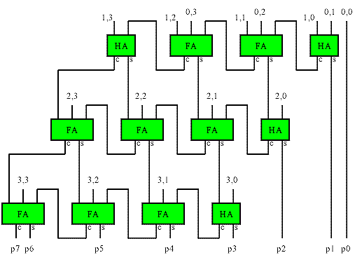
This basic structure is simple to implement in FPGAs, but does not make efficient use of the logic in many FPGAs, and is therefore larger and slower than other implementations.
{PICTURE}
Look-Up Table multipliers are simply a block of memory containing a complete multiplication table of all possible input combinations. The large table sizes needed for even modest input widths make these impractical for FPGAs.
The following table is the contents for a 6 input LUT for a 3 bit by 3 bit multiplication table.
| 000 | 001 | 010 | 011 | 100 | 101 | 110 | 111 | |
|---|---|---|---|---|---|---|---|---|
| 000 | 000000 | 000000 | 000000 | 000000 | 000000 | 000000 | 000000 | 000000 |
| 001 | 000000 | 000001 | 000010 | 000011 | 000100 | 000101 | 000110 | 000111 |
| 010 | 000000 | 000010 | 000100 | 000110 | 001000 | 001010 | 001100 | 001110 |
| 011 | 000000 | 000011 | 000110 | 001001 | 001100 | 001111 | 010010 | 010101 |
| 100 | 000000 | 000100 | 001000 | 001100 | 010000 | 010100 | 011000 | 011100 |
| 101 | 000000 | 000101 | 001010 | 001111 | 010100 | 011001 | 011110 | 100011 |
| 110 | 000000 | 000110 | 001100 | 010010 | 011000 | 011110 | 100100 | 101010 |
| 111 | 000000 | 000111 | 001110 | 010101 | 011100 | 100011 | 101010 | 110001 |
Partial Products LUT multipliers use partial product techniques similar to those used in longhand multiplication (like you learned in 3rd grade) to extend the usefulness of LUT multiplication. Consider the long hand multiplication:
|
67 |
|
67 |
|
67 |
|
67 |
By performing the multiplication one digit at a time and then shifting and summing the individual partial products, the size of the memorized times table is greatly reduced. While this example is decimal, the technique works for any radix. The order in which the partial products are obtained or summed is not important. The proper weighting by shifting must be maintained however.
The example below shows how this technique is applied in hardware to obtain a 6x6 multiplier using the 3x3 LUT multiplier shown above. The LUT (which performs multiplication of a pair of octal digits) is duplicated so that all of the partial products are obtained simultaneously. The partial products are then shifted as needed and summed together. An adder tree is used to obtain the sum with minimum delay.
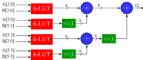
The LUT could be replaced by any other multiplier implementation, since LUT is being used as a multiplier. This gives the insight into how to combine multipliers of an arbitrary size to obtain a larger multiplier.
The LUT multipliers shown have matched radices (both inputs are octal). The partial products can also have mixed radices on the inputs provided care is taken to make sure the partial products are shifted properly before summing. Where the partial products are obtained with small LUTs, the most efficient implementation occurs when LUT is square (ie the input radices are the same). For 8 bit LUTs, such as might be found in an Altera 10K FPGA, this means the LUT radix is hexadecimal. For 4 bit LUTs, found in many FPGA logic cells, the ideal radix is 2 bits (This is really the only option for a 4 LUT: a 1 bit input reduces the LUT to an AND gate, and since each LUT cell has 1 output, it can only use one bit on the other input).
A more compact but slower version is possible by computing the partial products sequentially using one LUT and accumulating the results in a scaling accumulator. Note that in this case, the shifter would need a special control to obtain the proper shift on all the partials
A partial product multiplier constructed from the 4 LUTs found in many FPGAs is not very efficient because of the large number of partial products that need to be summed (and the large number of LUTs required). A more efficient multiplier can be made by recognizing that a 2 bit input to a multiplier produces a product 0,1,2 or 3 times the other input. All four of these products are easily generated in one step using just an adder and shifter. A multiplexer controlled by the 2 bit multiplicand selects the appropriate product as shown below. Unlike the LUT solution, there is no restriction on the width of the A input to the partial product. This structure greatly reduces the number of partial products and the depth of the adder tree. Since the 0,1,2 and 3x inputs to the multiplexers for all the partial products are the same, one adder can be shared by all the partial product generators. This structure works well in coarser grained FPGAs like the Xilinx 4K series.
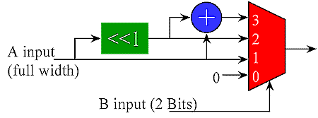
2 x n bit partial product generated with adder and
multiplexer
ADD VIRTEX COMPUTED partial product
A full multiplier accepts the full range of inputs for each multiplicand. If one of the multiplicands is a constant, then it is far more efficient to construct a times table that only has the column corresponding to the constant value. These are known as constant (K) Coefficient Multipliers or KCM's. The example below multiplies a 5 bit input (values 0 to 31) by a constant 67. Note that with a constant multiplier, all of the LUT inputs are available for the variable multiplicand. This makes the KCM more efficient than a full multiplier (fewer partial products for a given width).
| 5 bit input * 67 | ||||
| input | 00 | 01 | 10 | 11 |
|---|---|---|---|---|
| 000 | 0 | 536 | 1072 | 1608 |
| 001 | 67 | 603 | 1139 | 1675 |
| 010 | 134 | 670 | 1206 | 1742 |
| 011 | 201 | 737 | 1273 | 1809 |
| 100 | 268 | 804 | 1340 | 1876 |
| 101 | 335 | 871 | 1407 | 1943 |
| 110 | 402 | 938 | 1474 | 2010 |
| 111 | 469 | 1005 | 1541 | 2077 |
When the LUT does not offer enough inputs to accommodate the desired variable width, several identical LUTs may be combined using the partial products techniques discussed above. In this case, the constant multiplicand is full width, so the partial products will be m x n where m is the number of LUT inputs and n is the width of the constant.
In signal processing, there are often instances where one multiplicand is taken from of a small set of constant values. In these cases, the KCM multiplier can be extended so that the LUT contains the times tables for each constant. One or more of the LUT inputs select which constant is used, while the remaining inputs are for the variable multiplicand. The example below is a 6 LUT containing times tables for the constants 67 and 85. One bit of the input selects which times table is used. The remaining inputs are the 5 bit variable multiplicand (values from 0 to 31). Again, the input width can be extended using the partial product techniques discussed previously.
| 5 bit input * 67 | 5 bit input * 85 | |||||||
| 000 | 001 | 010 | 011 | 100 | 101 | 110 | 111 | |
|---|---|---|---|---|---|---|---|---|
| 000 | 0 | 536 | 1072 | 1608 | 0 | 680 | 1360 | 2040 |
| 001 | 67 | 603 | 1139 | 1675 | 85 | 765 | 1445 | 2125 |
| 010 | 134 | 670 | 1206 | 1742 | 170 | 850 | 1530 | 2210 |
| 011 | 201 | 737 | 1273 | 1809 | 255 | 935 | 1615 | 2295 |
| 100 | 268 | 804 | 1340 | 1876 | 340 | 1020 | 1700 | 2380 |
| 101 | 335 | 871 | 1407 | 1943 | 425 | 1105 | 1785 | 2465 |
| 110 | 402 | 938 | 1474 | 2010 | 510 | 1190 | 1870 | 2550 |
| 111 | 469 | 1005 | 1541 | 2077 | 595 | 1275 | 1955 | 2635 |
The shift-add multiply algorithm essentially produces m 1xn partial products and sums them together with appropriate shifting. The partial products corresponding to '0' bits in the 1 bit input are zero, and therefore do not have to be included in the sum. If the number of '1' bits in a constant coefficient multiplier is small, then a constant multiplier may be realized with wired shifts and a few adders as shown in the 'times 10' example below.
0 0000000 |
 |
In cases where there are strings of '1' bits in the constant, adders can be eliminated by using Booth recoding methods with subtractors. The 'times 14 example below illustrates this technique. Note that 14 = 8+4+2 can be expressed as 14=16-2, which reduces the number of partial products.
0 0000000 |
0 0000000 |
 |
Combinations of partial products can sometimes also be shifted and added in order to reduce the number of partials, although this may not necessarily reduce the depth of a tree. For example, the 'times 1/3' approximation (85/256=0.332) below uses less adders than would be necessary if all the partial products were summed directly. Note that the shifts are in the opposite direction to obtain the fractional partial products.

Clearly, the complexity of a constant multiplier constructed from adders is dependent upon the constant. For an arbitrary constant, the KCM multiplier discussed above is a better choice. For certain 'quick and dirty' scaling applications, this multiplier works nicely.
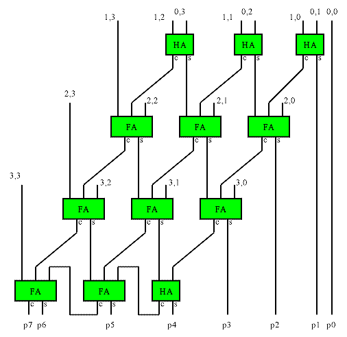
A Wallace tree is an implementation of an adder tree designed for minimum propagation delay. Rather than completely adding the partial products in pairs like the ripple adder tree does, the Wallace tree sums up all the bits of the same weights in a merged tree. Usually full adders are used, so that 3 equally weighted bits are combined to produce two bits: one (the carry) with weight of n+1 and the other (the sum) with weight n. Each layer of the tree therefore reduces the number of vectors by a factor of 3:2 (Another popular scheme obtains a 4:2 reduction using a different adder style that adds little delay in an ASIC implementation). The tree has as many layers as is necessary to reduce the number of vectors to two (a carry and a sum). A conventional adder is used to combine these to obtain the final product. The structure of the tree is shown below. The red numbers after each full adder in the illustration indicate the bit weights of each signal. For a multiplier, this tree is pruned because the input partial products are shifted by varying amounts.
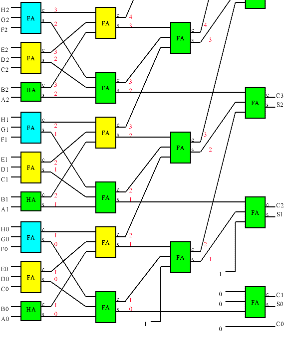
A section of an 8 input wallace tree. The wallace tree combines
the 8 partial product inputs to two output vectors corresponding to a sum
and a carry. A conventional adder is used to combine these outputs
to obtain the complete product..
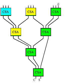 If you trace the bits in the tree (the tree in the
illustration is color coded to help in this regard), you will find that the
Wallace tree is a tree of carry-save adders arranged as shown to the left.
A carry save adder consists of full adders like the more familiar ripple
adders, but the carry output from each bit is brought out to form second
result vector rather being than wired to the next most significant bit.
The carry vector is 'saved' to be combined with the sum later, hence the
carry-save moniker.
A Wallace tree multiplier is one that uses a Wallace tree to combine the partial products from a field of 1x n multipliers (made of AND gates). It turns out that the number of Carry Save Adders in a Wallace tree multiplier is exactly the same as used in the carry save version of the array multiplier. The Wallace tree rearranges the wiring however, so that the partial product bits with the longest delays are wired closer to the root of the tree. This changes the delay characteristic from o(n*n) to o(n*log(n)) at no gate cost. Unfortunately the nice regular routing of the array multiplier is also replaced with a ratsnest.
To the casual observer, it may appear the propagation delay though a ripple adder tree is the carry propagation multiplied by the number of levels or o(n*log(n)). In fact, the ripple adder tree delay is really only o(n + log(n)) because the delays through the adder's carry chains overlap. This becomes obvious if you consider that the value of a bit can only affect bits of the same or higher significance further down the tree. The worst case delay is then from the LSB input to the MSB output (and disregarding routing delays is the same no matter which path is taken). The depth of the ripple tree is log(n), which is the about same as the depth of the Wallace tree. This means is that the ripple carry adder tree's delay characteristic is similar to that of a Wallace tree followed by a ripple adder! If an adder with a faster carry tree scheme is used to sum the Wallace tree outputs, the result is faster than a ripple adder tree. The fast carry tree schemes use more gates than the equivalent ripple carry structure, so the Wallace tree normally winds up being faster than a ripple adder tree, and less logic than an adder tree constructed of fast carry tree adders. An ASIC implementation may also benefit from some 'go faster' tricks in carry save adders, so a Wallace tree combined with a fast adder can offer a significant advantage there.
Many FPGAs have a highly optimized ripple carry chain connection. Regular logic connections are several times slower than the optimized carry chain, making it nearly impossible to improve on the performance of the ripple carry adders for reasonable data widths (at least 16 bits). Even in FPGAs without optimized carry chains, the delays caused by the complex routing can overshadow any gains attributed to the Wallace tree structure. For this reason, Wallace trees do not provide any advantage over ripple adder trees in many FPGAs. In fact due to the irregular routing, they may actually be slower and are certainly more difficult to route.
Booth recoding is a method of reducing the number of partial products to be summed. Booth observed that when strings of '1' bits occur in the multiplicand the number of partial products can be reduced by using subtraction. For example the multiplication of 89 by 15 shown below has four 1xn partial products that must be summed. This is equivalent to the subtraction shown in the right panel.
1 1011001 |
1 -1011001 |
This section on Booth multipliers will be expanded in the next release of this page.
| file: /Techref/logic/multiply.htm, 48KB, , updated: 1999/7/7 08:30, local time: 2025/9/23 02:06,
216.73.216.183,10-2-29-165:LOG IN
|
| ©2025 These pages are served without commercial sponsorship. (No popup ads, etc...).Bandwidth abuse increases hosting cost forcing sponsorship or shutdown. This server aggressively defends against automated copying for any reason including offline viewing, duplication, etc... Please respect this requirement and DO NOT RIP THIS SITE. Questions? <A HREF="http://techref.massmind.org/techref/logic/multiply.htm"> Multiplication in FPGAs</A> |
| Did you find what you needed? |
Welcome to massmind.org! |
|
Ashley Roll has put together a really nice little unit here. Leave off the MAX232 and keep these handy for the few times you need true RS232! |
.