Before the 3-chip was a 3-chip descrambler
I lived in an area where Zenith ZTACs
(2601s) were used to encode video signals on premium channels. In 1990 I
started designing my own ZTAC descrambler and built one using about 60 chips!
(pictures to follow). I spent a little over a year designing and adjusting
my SSAVI monster. After reducing the part count to 10-20 chips it was still
to much of a burden to build such a device in volume. One day I got the idea
to look in my business directory so I started calling Cable Television
warranty shops. After a few tries, I *socially engineered* 50 ZTACs
for $35 ea out of a shop as they felt I was not a threat to any of their
clients. When I received the 50 ZTACs I designed the
2-wire test chip to provide
a cheap, easy way to *test* these units (for educational purposes only).
In the load of the 50 ZTACs I got a letterhead from the cable company which
sold the 50 ZTACs to the warranty shop. Well, I decided its now or never,
so I created a company which remanufactured Zenith converters in NY (no,
I am not going to give out it's name) and called the manager of the Cable
Company to inquire about more ZTACs. After 30 minutes of social engineering
the manager decided to sell me 72 more ZTACs at $15 ea. Heaven. I told the
cable company I was unlike other warranty shops as I pay in advance for all
orders, will take any volume at a moments notice(gulp), and will purchase
complete systems. Well, after receiving the 72 ZTACs I got a call from the
manager to see if I would take another 862 ZTACs (wow!) ; at $12ea. Well,
the next day I sent off a large (well, at the time) certified check and a
week later 3000 pounds of ZTACs arrived. I made an agreement with the MSO
that I purchase ALL ZTACs they had (as they were upgrading). Over the following
months I purchased a few thousand ZTACs until the "well" went dry. I now
had many large customers and no ZTACs. Hence, an easy, cheap, ZTAC solution
has to be found in order to accomidate my happy customers. A few months after
all *reasonably* priced ZTACs were purchased I had to do something so I went
back to my mother of a home-built ZTAC and decided to redesign and re-examine
my approach. As I do most of my work on paper, I will describe in this document
the steps I took to create, tune, and finalize the 3-chip descrambler. To
ensure we are all thinking on the same wavelength I am first going to discuss
the fundamentals of NTSC video. (I got some good pictures on other web sites
to demonstrate.)
What is NTSC?
The relationships between vertical, horizontal, and
subcarrier components within a video signal are established by RS-170A (NTSC).
For proper lockup (shift-free viewing), these relationships must be maintained
throughout any descrambler.
Video: We should start with some background about
the NTSC video signal.
NTSC video displays 29.97 frames per second. Each frame is made up of two fields yielding a total of 59.94 fields per second. Each field consists of 262.5 horizontal lines scanned across the field from left to right, top to bottom, at a rate of 15,734.2637 per second. The half line at the end of the first field and at the beginning of the second field causes the lines of the two fields to "interlace." The two interlaced fields combine to form a frame made up of 525 distinct scan lines (figure 1).
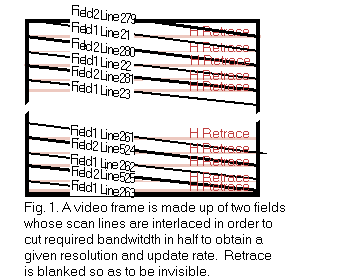
This clever system updates the image viewed on a TV screen
~60 times per second to avoid a flickering or jumpy appearance, provides
525 scan lines for good resolution, and yet requires one half of the bandwidth
of a non-interlaced system with the same image update rate and resolution
characteristics.
It is important to note that our discussion of NTSC pertains
to an "unmodulated" video signal. An unmodulated video signal compares to
a modulated video signal in the same way as an unmodulated audio signal compares
to an AM radio signal. Modulated signals must be received by a tuner in either
your audio system or TV. Unmodulated signals must be provided directly to
your audio or video system via what engineers call "base band" inputs.
The base band video signal is a voltage measured in IRE
units. There are 140 IRE per volt. As the voltage approaches 100 IRE the
picture becomes brighter. As the voltage falls to 7.5 IRE the picture approaches
black. During retrace (the time during which the picture tube's electron
beam returns to the left after scanning a line or to the top after scanning
a field) the signal drops to 0 IRE in order to "blank" the beam and make
the retrace invisible. Sync pulses contained within the blanking interval
fall to -40 IRE. The -40 to 100 IRE range corresponds to a one volt peak-to-peak
signal (between -0.286 to 0.714 VDC if the signal is properly clamped).
RS-170A alters and augments RS-170 to enable color video
transmissions. The key component is the addition of a color subcarrier signal
to the monochrome signal to specify the color hue and saturation of objects
in an image.
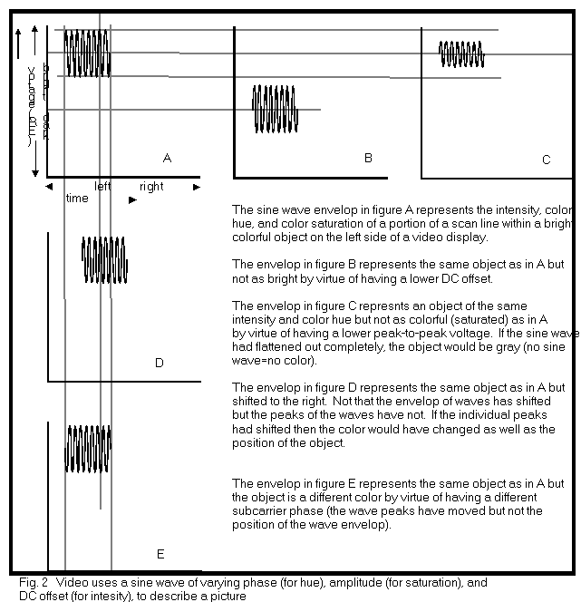
The color subcarrier is a 3,579,545±10 Hz sine wave impressed upon the monochrome signal. The net effect is that the video signal is a sine wave of varying amplitude, DC offset, and phase (see figure 2). The amplitude (peak-to-peak size) of the sine wave describes how deeply an object in an image is saturated with color (is it deep red or just a hint?). As the peak-to-peak voltage of the sine wave increases the displayed color becomes deeper. The phase (precise timing) of the sine wave describes the hue of the object (is it red, blue or some other color?). The DC offset voltage of the sine wave determines how bright an object is. As the offset voltage increases the displayed object becomes brighter.
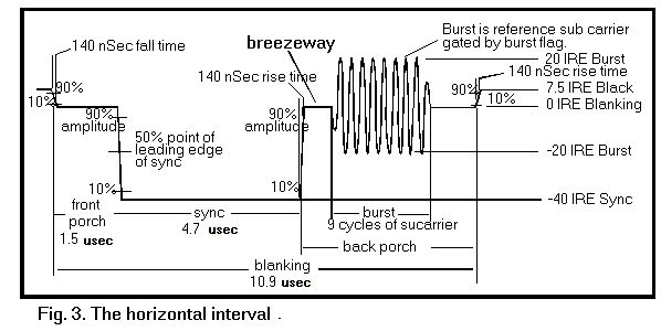
To determine color hue and saturation, video monitors
and other color decoding equipment compare the color subcarrier's phase and
amplitude with a reference signal. The reference signal is called the "burst"
and is transmitted in the video signal during the blanked retrace period
between horizontal lines known as the horizontal interval (figure 3).
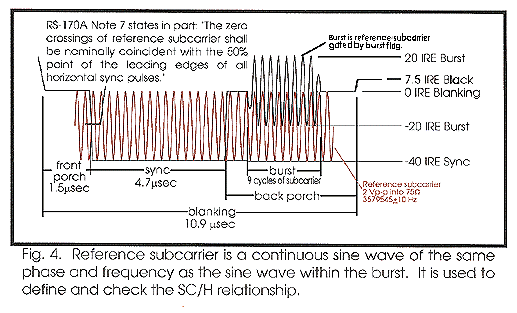
Specific Relationships: The burst defines a sine wave of 40 IRE peak-to-peak amplitude and 180° phase. The timing of the burst relative to horizontal sync (called SC/H Phase) is clearly defined by RS-170A Note 7 (see figure 4). The horizontal and color subcarrier frequencies were chosen so that there are 227.5 cycles of the subcarrier sine wave during the entire horizontal line (including blanking). The half cycle causes the phase of the burst to alternate 180° with each successive scan line within a field. Alternating the relationship in this manner minimizes the visibility of the color subcarrier within the brightness components of the picture.
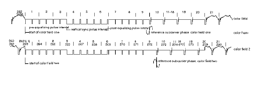
Subcarrier's timing relationship with the rest of the video signal is defined by NTSC during the vertical interval which spans a period equivalent to 20 horizontal lines at the beginning of each field (see figure 5). There are 59.94 color fields and 29.97 color frames per second. The starts of color field one is defined by a whole line between the first equalizing pulse and the preceding horizontal sync pulse. The start of color field two is defined by a half line between the first equalizing pulse and the preceding horizontal sync pulse. These half lines give rise to interlacing.
The relationships between components within the NTSC
video signal are complex, fragile, and important. A descrambler must be carefully
designed, built, and used in order for these relationships to remain intact.
If not, problems will creep in to the finished descrambled video
product.
At the time of design I decided to build a "descrambler" using minimal parts so volume production could be attained at a low cost. In order to build a descrambler with few parts there must be an intelligent part (like a microcontroller) and a few other parts to feed it information it would need to reconstruct video. In looking at the NTSC standard, let's examine what kind of information we would need to collect in order for a microcontroller to *understand* it's surroundings.
NTSC Issues:
1. How to detect the horizontal blanking interval with
normal and sync-supressed video.
2. Where are we in the frame? Best way to find out.
3. Simple video clamp.
Descrambling Issues:
1. Should I just shift the sync or re-insert it?
2. How to best capture data (cheaply)
3. Invert the video for under $.50.
4. Run all the above while trying to create a video
frame.
5. Create a list of priorities in the 3-chip descrambler
world.
For the NTSC issues we shall look at parts of the schematic
of the 3-chip to see how all three issues were resolved.
1. How to detect the horizontal blanking interval with normal and sync-supressed video.
1. Most importantly, how do I tell where the horizontal
blanking interval is in both suppressed and normal sync? The EASY answer
might be the color burst. After repeated attempts by people to use the color
burst and the incredible cost to lock on such a *small* signal I felt it
would be pointless to do so. I therefore determined that another not-so-apparant
pattern in NTSC video was the fact that the SYNC portion of the video had
to have a VERY fast fall and rise time (like 150nS). Since this is the ONLY
pattern of fast rise and fall in a video line over time I chose this to be
the method for finding a horizontal blanking interval.
The circuit:
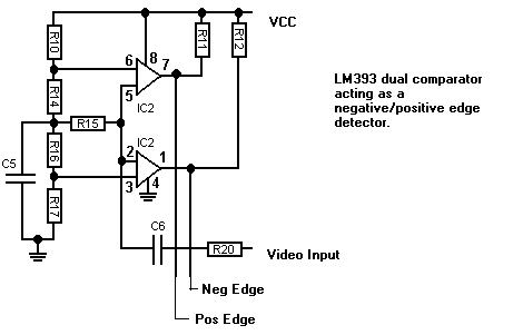
Figure 6.
A closer look at the negative edge detector (with only black video present):
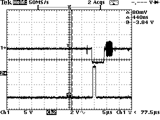
Negative Edge in the Real World (real moving video)
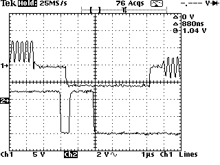
How Negative Edge works on scrambled video:
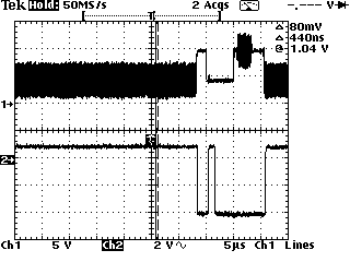
Now, a look at the Posistive Edge Detector:
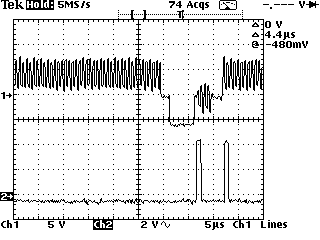
A look at the positive detector on a scramble line of video:
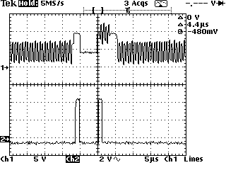
As you can see from the above waveforms that we can sync
up our circuit using the positive and negative edge detects as it ALWAYS
occurs in the same place for both normal and sync-supressed syncs.
2. Where are we in the frame? Best way to find out.
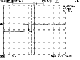
This one took some thought. The NTSC standard recommends using the last line of the field to determine which field in the frame you are looking at. Since we have a neg/pos detector it would only be reasonable to look for some other event that happens which could be EASILY detected while we create a line. Line 6 of the second field offers an interesting (short time) detectable signal. Look below:
Positive Edge Detect:
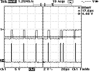
Negative Edge Detect:
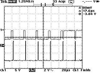
Notice this whole event lasts ONLY 7uS (perfect for a
few reads from a port on a PIC)
Looking through the commented code you will find
3. Simple video clamp.
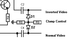
So the video does not float everywhere I kind of needed to design a type of clamp which would keep the video in one place even though the dc reference was lost. This was rather simple as I chose to "reinsert" the sync rather than lower it (see descrambler challenges). The clamp control is low ONLY when sync is present, and the entire VBI. The circuit below shows the clamp circuit with the invert amplifier (for circuit reference):
This is the clamping action during 3 lines of video.
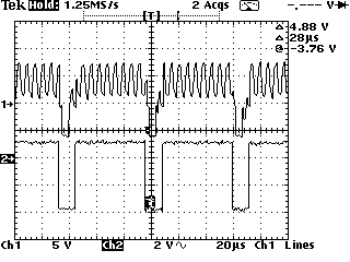
This is how the clamp works from the last sync of field
1 to the vertical blanking interval of field 2.
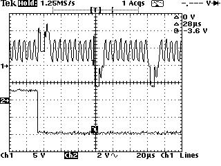
The above demonstrates a simple clamp worth no more than
$.12. Mission accomplished.
Now comes the mean stuff. Descrambling issues.
1. Should I just shift the sync or re-insert it?
This one took a while to figure out. If I reinsert the sync will it happily co-exist with now foreign video? Will the color burst get hacked on video which is not up to spec? Will the sync to video relationships get screwed up even with a clamp? Well, after some experimenting the answer is no. I found that if this unit was to CREATE TWO frames of video and then so to speak SHIFT that frame UNTIL it matches with the original video AND can be dynamic enough to allow for small timing differences there should be no problem. Easier said than done. This brought about my worst nightmare. Build a circuit which can essentially rebuild the sync including the front porch, back porch, sync, and re-insert the color burst. (That's easy part). Timing all those decisions in a PIC was rough. Below is the circuit which re-creates the sync from scratch:
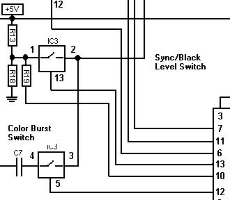
R19 controls either SYNC or BLACKLEVEL for the sync.
(front porch, back porch, sync)
The color burst switch controls a switch allowing the
chroma signal to pass
Below is the R19 Sync/BlackLevel Control.
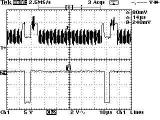
The actual NEW sync at pin 1 of the switch looks like
this:
(notice the color burst at pin 1, WHY? Well look at the
commented code
The best way to ensure the color burst was at the SAME
BLACK LEVEL
was to actually open the color burst switch and the SYNC
SWITCH (BLACKLEVEL SELECTED)
at the same time. This essentially placed the color burst
at the same level as the black level thereby
making a happy :-) final sync.
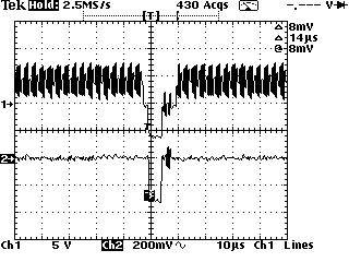
2. How to best capture data (cheaply)
First let's look at the data we need to capture (for invert and HL10-13 data):
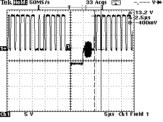
Fortunately the data has fast slew rates so we can use
our neg/pos edge detector to tell us if there is data.
In the commented source code you will find that this
data on Lines 10 through 13 is used to determine if
we are on a SSAVI channel and if we should sample line
20.
Well, the negative or positive edge detector work WELL for fast slew rates. Look below:
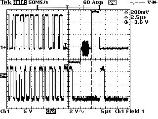
(trace 2 is the negative edge detector)
Below is Line 20 (the active invert line) and with it
on trace two is the negative edge detector.
Notice how we can use the neg/pos edge detector not only
for lockup but also inversion/
data.
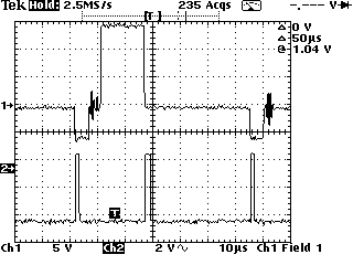
Using a simple polling procedure of the negative edge
detector on line 20 we can determine whether this field
is inverted or not (this field is normal video).
This is what the negative edge detector outputs for INVERTED
video:
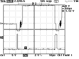
(Note: You are looking at line 20 with my ZTAC headend
in INVERT mode on SSAVI.
Well, that's a cheap method for detecting inversion/data
$0.00 (cost absorbed in sync correction)
3. Invert the video for under $.50.
Here is the circuit:
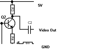
Pretty simple, Q2 is the cheapest transistor around (general
purpose).
Now for the contest. Design an amplifier using ONLY transistors for input, inversion, and output (follower). The circuit which best passes normal video/inverted with the least distortion and part count (cost) wins. Your design MUST work in the exsisting 3-chip descrambler and will replace ALL current transistor amplifiers.
The prize is $100 and a free kit (or a free kit for the new 3-chip member). I am taking all costs for this contest out of my pocket, so it will not cost this project a dime.
All entries will get posted on this website and the winners design will be incorporated in the new 2-chip descrambler (ooppss)?
Please submit all entries by November 1,1998.
Judges will be selected amoung engineers not participating in the contest.
May the cheapest, clearest, easiest to build design
win!
Now that you know what the circuit does lets look at
commented code, line by line.
The code is VERY difficult to read so I have made MANY
pictures so ALL of you can make changes you need. There are many routines
to accomplish the rebuilding of video and make decisions. The program consists
of a MAIN program which is an endless loop creating 2 fields of a video signal.
MAKEHLINE actually makes a horizontal sync, line, inverts the video, checks
for inverted video, changes the VCO, etc. MAKEHALFLINE creates the halfline
..... SETMODE makes decisions based on information gathered in HLINE like
..... MAKEVBI makes the vertical blanking interval. We will look at the most
complex routine first MAKEHLINE (make horizontal line), this will give you
an idea what is going on inside the 3-chip most of the time.
;3chip.src rev
4
;
;
; MAKEHLINE
;
;
; Port A
; 0 - PLL frequency control
; 1 - VidLevel - an experimental port used to try and
clamp video better (not used in this code)
; 2 - Troubleshooting
; 3 - Manual Invert control (MANUALINVERT)
; Port B
; 0 - VNX- Normal Video Switch
(this passes video through to output as it comes in)
; 1 - CLV- Clamp Voltage (this
selects 0=0V and 1=2.5V)
; 2 - NED- Negative Edge Detect
(rapid falling signal)
; 3 - PED- Positive Edge Detect
(rapid rising signal)
; 4 - BSV- Black/Sync Voltage
(Black =1 , Sync = 0)
; 5 - VIX- Inverted
Video Switch (this passes the inverted video from Q2)
; 6 - BUX- Burst Switch (this
passes the burst through, which is AC coupled so it can be clamped!)
; 7 - BSX- Black Level/Sync
Switch
; SOME USEFUL EQUATES
;
; MAKESYNC = BSX (just make sync level)
; MAKEBURST = BSV + BUX + BSX (this puts the
BURST right on the black level)
; PASSVIDEO = VNX + CLV + BSV (normal video
passes, its clamped, Black Voltage)
; PASSINVERT = CLV + BSV + VIX (inverted video
passes, its clamped, Black Voltage)
; PASSBLACK = BSV + BSX (video is just black
level)
;
;
;
;
; NED = 00000100b - Negative Edge Detector
; PED = 00001000b - Positive Edge Detector
;
; BIT EQUATES
;
VIDEOKAY
EQU MODE.0 - if 1 then 3-chip is genlocked
onto video signal
; VIDEOINVERT EQU
MODE.1 - invert the video during active lines
; VIDEOBLACK
EQU MODE.2 - make the video black during
active lines
; WANTSINVERT
EQU MODE.7 - user wants to invert
video
; MANUALINVERT
EQU PORTA.3
;Description of Variables
; MODE defines the mode the unit is currently
in (look above for specifics)
; OscDecision holds the value of the NED+PED
for running the oscillator during a sample time after negedge.
; FastCnt is incremented every time the oscillator
is sped up, if it is sped up 128 times then it concludes that
;
we are no where near locking up and invokes a code timing adjustment of .2uS
(faster lockup)
; SlowCnt (same as fastcnt) but used to quickly
slow down oscillator.
; temp is a crap var for counting, etc...
; Data is a place to store the result if data
was actually found on the line (HL10 to HL13)
; Line6 holds temp data telling if we found
field 2 , line 6 (line6=ped+ned if found)
; isInverted tells the main program if the line
was inverted/not (0 = inverted) (HL 20)
; FindLine6 (PED bit) is set if we dont
know where we are and MakeHLine has to find Field2, line 6
; makelines is passed to this routine telling
it how many Hlines to build...
MAKEHLINE
movlw MAKESYNC ; normally make
sync (horizontal sync pulse)
btfss
VIDEOKAY ; IF 3-chip is not locked on THEN
movlw PASSVIDEO ; let video pass
through (errors)
movwf
PORTB ; Start
hsync pulse (cool)
movlw 00001100b ; read
comparitors (rise/fall) , everything else out.
tris
PORTB ;
; turn on my troubleshooting pulses
movlw 11111011b
tris
porta
; turn on my troubleshooting pulses
bsf
troubleshoot
bcf
troubleshoot ; pulse 1 on OSCILLOSCOPE
;
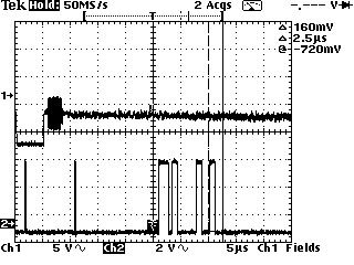
Look below at the FIRST pulse, this is where we are in a line
nop
; sample the negative edge of the comparitor
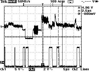
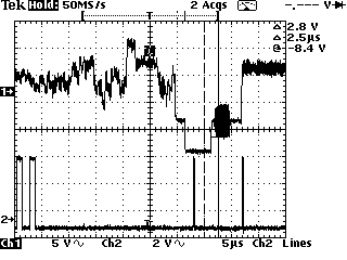
The following description of the code and how it maintains lock is incorrect. A corrected description will follow this one.
**********************************************************************
;
the code below works as follows: (O = OscDecision)
;
if the neg. edge of a horizontal sync is detected in section A but not B
then O.2 is 0 (slow down oscillator)
;
if the neg. edge of a horizontal sync is detected in section A and B then
O.2 is 1 (speed up oscillator)
;
if the neg. edge of a horizontal sync is detected in section B but not A
then O.2 is 1 (speed up oscillator)
;
if the neg. edge of a horizontal sync not detected in either section then
O.2 is 1 (speed up oscillator)
;
if the pos. edge of a horizontal sync is detected then O.3 is 1 (slow down
oscillator)
;
;
;
in other words, if the neg pulse is found in A but not B then we are doing
good, slow down and let it
;
cross into section b so we can speed it up again! (*** Wrong
***)
;
This provides a very accurate PLL.
;
section a
movf PORTB, 0
; samples for negative edge of hsync
iorwf PORTB, 0
iorwf PORTB, 0 ;
xorlw
NED
;
;
section b
iorwf PORTB, 0 ; There
should be no neg here if we are on time...
iorwf PORTB, 0 ; There
is some delay until edge detect
iorwf PORTB, 0
; will return back to normal.
iorwf PORTB, 0
iorwf PORTB, 0
iorwf PORTB, 0
iorwf PORTB, 0
movwf OscDecision ; this is where the final
sample is stored.
movlw MAKEBURST ; time to make the burst
btfss
VIDEOKAY ; IF video is not locked
up THEN
movlw PASSVIDEO ; just pass the video
movwf
PORTB ; Sync
up, let burst pass by
btfsc OscDecision,
NED ; IF negative edge found in
a & b (where it should not be) THEN
bsf PORTA,
0
; speed up oscillator 50Khz
btfss OscDecision,
NED ; ELSE (negative edge
found in section a but not b, where it should be)
bcf PORTA,
0
; slow down oscillator 50Khz
btfsc OscDecision,
PED ; IF we heard a positive edge
THEN
bcf PORTA,
0
; slow down oscillator 50Khz (were okay)
incf
FastCnt,1
; how often are we speeding up?
btfss OscDecision,
NED ; IF we are slowing down
THEN
clrf
FastCnt
; reset fast count
incf SlowCnt,
1
; how often are we slowing down?
btfsc OscDecision,
NED ; IF we are speeding up
THEN
clrf
SlowCnt
; reset SlowCnt
;
After 127 fast oscillators or 127 slow oscillators we have to do something
to speed this lockup!
;
Notice this routine provides .2uS of course code time tuning!
btfsc FastCnt, 7 ; IF we
have done 128 fast oscillators (1/2 a field) THEN
goto
ActiveLine
; use up .6uS total!
btfsc SlowCnt, 7 ; IF we have done
128 slow oscillators (1/2 a field) THEN
goto
ActiveLine
; use up 1.0uS total!
; IF we have done neither 128 fast or slow then we only use up .8uS
here
; Sync is OVER!
************************** Corrected Description ********************
To understand how lock is maintained, you need to understand the relationship of the PEDs/NEDs to the sync and to the code. The code speeds up the oscillator or slows it down depending on where it sees the NED. How does this affect the NED? It doesn't! The NED will happen at the falling edge of the sync regardless of how fast the oscillator is running. What changes with oscillator speed is WHEN we look for the NED. If the oscillator is running too fast, then we are looking for the NED too early and if the oscillator is running too slow then we are looking for the NED too late. The NED itself does not change! Magicboxes says that the NED should be locked to the transition from a to b or directly in front of the section b. Let's look at the code again and re-comment it.
; section a
movf PORTB,
0
; samples for negative edge of hsync
iorwf PORTB, 0
iorwf PORTB,
0
;
xorlw
NED
; If a NED was detected, then B2=0, if not then B2=1 because of
XOR
;
section b
iorwf PORTB, 0 ; There
should be no neg here if we are on time...
iorwf PORTB, 0 ; There
is some delay until edge detect
iorwf PORTB, 0
; will return back to normal.
iorwf PORTB, 0
iorwf PORTB, 0
iorwf PORTB, 0
iorwf PORTB, 0
movwf OscDecision ; If a NED was detected
in a (B2=0) and was not detected in b, then B2 remains 0
; If a NED was detected in a (B2=0) and was also detected in b, then B2=1, 0 or 1=1
; If a NED was NOT detected in a (B2=1) and was not detected in b, then B2=1
; If a NED was NOT detected in a (B2=1) and was detected in b, then B2=1, 1 or 1 =1
movlw MAKEBURST ; time to make the burst
btfss
VIDEOKAY ; IF video is not locked
up THEN
movlw PASSVIDEO ; just pass the video
movwf
PORTB ; Sync
up, let burst pass by
btfsc OscDecision,
NED ; If B2=1(see conditions
above) then
bsf PORTA,
0
; speed up the osc 2khz(not even close to 50 Khz)
btfss OscDecision,
NED ; ELSE (negative edge
found in section a but not b, where it should be)
bcf PORTA,
0
; slow down oscillator 2Khz
btfsc OscDecision,
PED ; IF we heard a positive edge
THEN
bcf PORTA,
0
; slow down oscillator 50Khz (were okay)
Magicboxes assumes that if we see a NED in both a and b that the oscillator is going too slow and should be speeded up. If we speed it up, what will happen to the relationship between the NED and the a and b sections of the code? Remember, the NED will stay the same and WHEN we sample (the a and b sections) will shift to the left because the code executes faster and the a and b sections will happen earlier. Eventually, the a and b sections will shift to the left far enough that the NED is only in section b. This will still give us a "1" at OscDecision and will keep the oscillator speeded up. Eventually, the a and b section will shift to the left until the NED is not in either section, which STILL keeps the oscillator in the fast mode. At this point, we have lost lock and the a and b sections will shift left until a new sync comes along. Eventually, the a and b sections will find the next sync and the a section will move into the NED. Aha, at this point, in a and not in b, the OscDecision will switch to "0" and slow the oscillator down. The a and b sections will now shift to the right(code is executing slower) until the a section (and b section)is no longer in the NED. The OscDecision will switch back to "1" and speed up the oscillator. This is the point that the 3chip actually locks at. The trailing edge of the NED is locked to the START of the A section, not the a/b junction. If the oscillator locks to the a section alone, then what purpose does the b section serve. NONE!! The b section of code does nothing and merely confuses an already confusing piece of code. Compare this section of code with NTSC rev7t1a or PAL code and you will see that they all do the same thing, lock on the beginning of the a section. Some of Jens' PAL code actually locks on the PED at the end of the sync instead of the NED at the start of the sync.
ActiveLine
movlw
PASSVIDEO ; If invert/black level
fails then pass normal video
btfsc VIDEOINVERT
; IF video invert flag (in mode) is set THEN
movlw PASSINVERT ;
pass inverted video
btfsc
VIDEOBLACK ; IF video blackout flag (in mode)
is set THEN
movlw PASSBLACK
; pass nothing
btfss
VIDEOKAY
; IF the 3-chip is NOT locked onto the signal then
movlw
PASSVIDEO ; only pass the
video
movwf
PORTB ; Set up
the active line with config from above
; setup the oscillator speed control
movlw 11111010b ; Enable the Oscillator
speed control to work
tris PORTA
bsf troubleshoot
bcf troubleshoot ; pulse 2 on TRACE
2
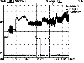
; we have A LONG WAY TO GO!
; next up, Finding our place in the field, find data, and inverted
video....
; FINDING THE DATA
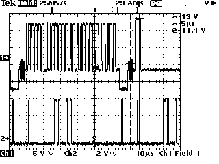
nop
movlw 17
movwf temp
movf PORTB, 0
; If this is line 6 then no transitions, if data both PED+NED are set!
sampleloop
iorwf PORTB, 0 ; check
for data for awhile.
decfsz temp,1
goto sampleloop
movwf
Data
; place to store the status of potential data found
; Where are we in the FRAME?
; You had better appreciate
this image as it only happens once! (a real pain).
; Below you will see an image
which will only every happen ONCE when you flip a channel:
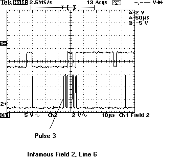
;
notice the dead video before pulse 3, In line 6 there should be nothing there
as above.
;
The following statement makes sure that
xorlw NED+PED ; (both this time)
movwf Line6 ; if we
are on line 6 then line6 = NED+PED (remember this for later!)
; CHECK FOR INVERTED VIDEO
bsf troubleshoot ; PULSE 3 - INVERT WINDOW
movf PORTB, 0
; Negative edge in line when field is not inverted
iorwf PORTB, 0
; These inclusive ors give us a healthy window
iorwf PORTB,
0
iorwf PORTB, 0
iorwf PORTB, 0
iorwf PORTB, 0
iorwf PORTB, 0
andwf isInverted, 1 ; isInverted.2 = 1 when
not inverted, 0 when inverted
bcf troubleshoot ; END OF PULSE
3
;
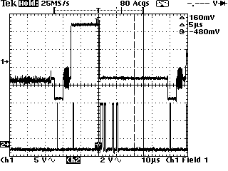
Look below at the figure. You are looking at Line 20 which controls invert.
As you can see the third
;
pulse window falls during the Invert level transition. If the pulse falls
as below, then the video is not inverted
;
and NED becomes 1 and isInverted.2=1 . If the video IS inverted
then this pulse does not change and
;
then NED would have been 0, then isInverted.2 = 0
nop
nop
;
BACK TO LINE 6
bsf troubleshoot ; PULSE 4 - LINE
6 RISING EDGE

movf PORTB, 0
; This detects line 6 rising (look at pulse 4 above)
iorwf PORTB, 0
iorwf PORTB, 0
iorwf PORTB, 0
bcf troubleshoot ; END OF
WINDOW
xorlw
NED
; This will make W= NED +PED if line 6 is rising here (which it is)
andwf Line6, 1 ; This
will keep LINE6 = NED+PED if we are on line 6.
; MANUAL INVERT
;
this routine is normally run throught this procedure as a NOP in all cases.
It simply reads the switch
;
and sets an invert flag if so.
btfss MANUALINVERT ; IF RA3 is 0 (button pushed) THEN
bsf WANTSINVERT ; set inversion flag
;
BACK TO LINE 6 STUFF
; this is between pulse 4 and 5 (notice the long quite area)
movf PORTB, 0
; Line 6 should have NO W bits set!
iorwf PORTB, 0
iorwf PORTB, 0
iorwf PORTB, 0
iorwf PORTB, 0
iorwf PORTB, 0
iorwf PORTB, 0
iorwf PORTB, 0
nop
xorlw PED+NED ; this will make PED+NED if on
line 6
andwf Line6, 1 ; line6=PED
+ NED if it is still line 6
nop
bsf troubleshoot ; PULSE 5 - FALLING
EDGE OF LINE 6

movf PORTB, 0
; Check for falling edge of line 6 (look at pulse 5 as above!)
iorwf PORTB, 0
iorwf PORTB, 0
iorwf PORTB, 0
bcf troubleshoot ; PULSE 5 - END OF THAT WINDOW!
xorlw
PED
; you guessed it !, W = PED +NED if on line 6
andwf Line6, 1 ; and
yes, line6 = PED+NED if still finding we are on line 6
btfss MANUALINVERT ; just bullshit as above, nops got boring..,
checking the switch again.. fun..
bsf WANTSINVERT ;
btfss MANUALINVERT ;
bsf WANTSINVERT ;
bsf troubleshoot ; PULSE 6 - LINE
6 RISING EDGE

movf PORTB, 0
; Check for rising edge again! (look at the last pulse, #6)
iorwf PORTB, 0
iorwf PORTB, 0
iorwf PORTB, 0
bcf troubleshoot ; END OF PULSE
6
nop
xorlw
NED ; w
= NED +PED if on line 6 (BTW if you now think
NED stands for Ned Flanders then please
; move away from your computer...)
andwf Line6, 1 ; line6 = NED+PED if on 6
; BLOW TIME, LINE 6

movlw 26
movwf temp
movf PORTB, 0
; Line 6 is quiet (if we are on line 6 - look above after pulse 6)
sampleloop2
iorwf PORTB, 0
decfsz temp, 1
goto sampleloop2
andwf Data, 1 ; why not, was there any data
there too?, and it on....
xorlw PED+NED ; you
know...
andwf Line6,
1 ; finally,
if we are on line 6 then line6=NED+PED
rlf Line6,
0 ; Move
NED to PED position in W
andwf Line6, 1 ; If
PED in here is 1 then we are on line 6!!!!!!!!!!!!!!!!!
rlf Data,
0
; Move NED to PED position in W
andwf Data,
1 ; If PED in
Data is 1 then we found data on this line!!!!
movf FindLine6, 0 ; Are we searching
for line6??????? (PED =1 if so)
andwf Line6,
1 ; Line6
(PED bit) is 1 if we have to now make up lines 7-10
btfsc FindLine6, PED ; IF we are looking for line
6 THEN
incf makelines, 1 ;
keep searching (add an extra line to create until we find it!)
movlw 11111011b
tris
PORTA ; Shut
off the Oscillator control
;
END OF THE ACTIVE LINE OF VIDEO
movlw PASSBLACK
btfss
VIDEOKAY ; IF 3-chip not locked
on THEN
movlw PASSVIDEO ; pass
normal video
movwf
PORTB ; create
front porch of next sync.
decf makelines, 1
btfsc
Z
; IF no more hlines to create THEN
retlw
1
; return to main pgm
nop
btfsc Line6,
PED ; IF Line6 found THEN
clrf
FindLine6
; Stop searching for it.
movlw 4
btfsc Line6,
PED ; Create 4 more lines (7-10) for main
pgm
movwf
makelines ;
goto MAKEHLINE
SETMODE
; Checks for vsync errors and sets FindLine6
nop
nop
btfsc Error,
PED
; IF there was an error from MAKEVSYNC THEN
incf ErrorCnt,
1
; add 1 to error counter
btfsc ErrorCnt,
2
; IF 4 errors THEN
bcf
VIDEOKAY
; stop descrambling
movf Error, 0
btfsc ErrorCnt, 2 ;
IF we have had 4 errors in a row THEN
movwf FindLine6
; look for line6
btfsc FindLine6, PED ; IF we are looking for line 6
THEN
clrf ErrorCnt
; restart counter
btfss Error, PED ;
IF there was not an error THEN
incf VideokayCnt, 1 ; increment the good video
counter
btfsc WANTSINVERT ; IF the user pressed the
invert switch THEN
bsf
DataLine12
; say we saw data on line 12
btfsc WANTSINVERT ; IF the user pressed
the invert switch THEN
bsf
DataLine13
; say we saw data on line 13
btfss
DataLine12
; IF no data on line 12 detected THEN
clrf
VideokayCnt
; clear the video okay counter
btfss DataLine13
clrf
VideokayCnt
btfsc VideokayCnt, 1 ; IF 2 good frames have
been heard THEN
bsf
VIDEOKAY
; then allow DECODING
btfsc VideokayCnt,1 ; IF 2 good frames have
been heard THEN
clrf VideokayCnt
; Clear this counter
movlw 41
movwf temp
modeloop1
decfsz temp, 1 ; waste
some time..
goto modeloop1
clrwdt
retlw
1
; BACK TO MAIN.
MAKEHALFLINE
; draws a halfline (end of field
one)
movlw MAKESYNC ; time to make the
sync
btfss
VIDEOKAY ; IF 3-chip not locked
on THEN
movlw PASSVIDEO ; just pass video
movwf
PORTB
; change mode.
nop
movlw 5
movwf temp
makehalflineloop1
decfsz temp, 1
goto
makehalflineloop1 ; waste
time..
nop
clrwdt
movlw MAKEBURST ; time to make the burst
btfss VIDEOKAY ; IF 3-chip is not
locked on THEN
movlw PASSVIDEO ; pass video
movwf
PORTB ; change
mode
movlw 5
movwf temp
makehalflineloop2
decfsz temp, 1
goto makehalflineloop2
movlw PASSBLACK ; time
to send black level
btfss
VIDEOKAY
; is the 3-chip bla bla bla not locked on then
movlw
PASSVIDEO
; pass video
movwf
PORTB
; change mode
goto
makehalfl1
; this is called tuning at 3AM in the morning.
makehalfl1
; I hated some writting some of this fricking code...
goto
makehalfl2
makehalfl2
goto
makehalfl3
makehalfl3
goto
makehalfl4
makehalfl4
movlw PASSBLACK ; This is called bad tuning
at 3am, this code does nothing but
btfss
VIDEOKAY ; was
used until I looked at my screwup here on a scope.
movlw PASSVIDEO ; kept this useless code
cuz I was too lazy to remove it...
movwf
PORTB ;
Useless
movlw 28
movwf temp
makehalfloop2
decfsz
temp, 1
goto makehalfloop2 ;waste some time
movlw PASSBLACK ; this was WORSE alignment than the above (probably
about 2am)
btfss
VIDEOKAY ; kept as I got fed up
with recalculating the above loop
movlw PASSVIDEO
movwf
PORTB ;
Useless
nop
nop
retlw
1
; back to MAIN
; Generates the vertical blanking interval
; makes sure we are actually writing this vsync
when the real one is happening
MAKEVBI
;
make 6 pre-equalizing pulses - Lines 1 to 3
movlw MAKESYNC ; time
to make sync level
btfss
VIDEOKAY
; IF 3-chip not locked THEN
movlw PASSVIDEO ; just
pass video
movwf
PORTB ; change
mode
bsf troubleshoot
nop
bcf
troubleshoot
movlw 2
movwf temp
makevbiloop1
decfsz
temp,1
makevbiloop1 ; waste time
movlw MAKEBLACK ; you
know, pass black if okay, pass video if not...
btfss VIDEOKAY
movlw PASSVIDEO
movwf
PORTB ; change
mode
movlw 45
movwf temp
makevbiloop2
decfsz
temp,1
goto makevbiloop2
movlw
6
; for the vsyncs next
movwf OscDecision ;
confusing but i recycled the variables
decfsz makelines, 1 ; have we made
6 yet???
goto MAKEVBI
; Now make 6 serrated vertical sync pulses -
Lines 4-6
; This is where we check for
errors!
bsf MODE,PED ; this is set for anding the result
later (a vsync pos det. mask)
makesync
movlw MAKESYNC ; make
vsync now...
btfss VIDEOKAY
movlw PASSVIDEO
movwf
PORTB ; change
mode
movlw 28
movwf temp
goto makevbi1
makevb1
goto
makevbi2
makevbi2
goto
makevbi3
makevbi3
goto
makevbi4
makevbi4
bsf
troubleshoot
;nop
clrw
nop
lookforpossync
iorwf PORTB, W ; sample
for vsync pulses
decfsz
temp, 1 ;
goto
lookforpossync
; pos sync detected during sample means we are not lined
up...
bcf troubleshoot ; nop
movwf
temp ;
crap
andwf Mode ; if we got an error then the PED
bit will be 1
movwf temp ; save the
result
movlw
2
; old code crap
btfsc temp, PED ; IF positive edge
was detected in vsync THEN
bcf Mode, PED ; clear the mask
bit we set earlier
btfsc temp,PED
bsf Error, PED ; set the
error bit, let SETMODE clean things
up
movlw PASSBLACK ; sync is over... pass black
btfss VIDEOKAY
movlw PASSVIDEO
movwf
PORTB ; make
mode change
movlw 4
movwf temp
makevbiloop3
decfsz
temp,1
goto
makevbiloop3 ; waste time
movlw 6
movwf makelines
decfsz OscDecision, 1 ; sorry
for the confusion, a recycled variable ...
goto makevsync
bsf
troubleshoot
;nop
; Lines 7-9 , post equalizing pulses.
makepost
movlw MAKESYNC
btfss VIDEOKAY
movlw PASSVIDEO
movwf
PORTB ; change
mode to sync again
clrwdt
bcf
troubleshoot ;nop
nop
movlw 2
movwf temp
makevbiloop6
decfsz
temp,1
goto
makevbiloop6 ; waste time
movlw PASSBLACK
btfss VIDEOKAY
movlw PASSVIDEO
movwf
PORTB ; change
mode to black if video okay
movlw 43
movwf temp
makevbiloop7
decfsz temp,1
goto makevbiloop7
decf makelines,1
btfsc Z ;IF we made all 6
THEN
retlw
1
; RETURN TO MAIN
goto makevbi10
makevbi10
goto
makevbi11
makevbi11
goto
makevbi12
makevbi12
goto
makepost
MAIN
movlw PASSVIDEO
movwf
PORTB ; allow
video to pass
movlw 00001100b ; setup port b
tris PORTB
movlw 11111111b ; port a is all reading
tris PORTA
clrf MODE ; do not try to decode
movlw 00001011b
option
; set up watchdog timer, prescaler to WDT, 1:8
MAKEFRAME
bcf
VIDEOINVERT ; disable
inverted video mode during MAKEHLINE
movlw
6
; for vbi, pre-equalizing pulses
movwf makelines
call
MAKEVBI
; Make FIELD 1 - LINES 1-9
clrf
DataLine
; this clears data heard in video lines (DataLine10 - DataLine15)
btfss WANTSINVERT ; IF user does not want inverted video
THEN
bsf VIDEOINVERT ; enable inverted
video
movlw 1
movwf makelines
call MAKEHLINE
; Line 10
btfsc Data,
PED ; IF
we heard data on line 10 THEN
bsf
DataLine10
; save that in DataLine10 bit
nop
movlw 1
movwf makelines
call MAKEHLINE
; Line 11
btfsc
Data,PED
; IF we heard data on line 11 THEN
bsf
DataLine11
; save it in bit dataline11
nop
movlw 1
movwf makelines
call MAKEHLINE ; Line 12
btfsc Data,
PED ; IF
we heard data on line 12 THEN
bsf
DataLines12 ; save it in
bit dataline12
nop
movlw 1
movwf makelines
call MAKEHLINE ; Line 13
btfsc
Data,PED
; IF we heard data on line 13 THEN
bsf
DataLine13 ;
save it in bit dataline13
nop
movlw 1
movwf makelines
call MAKEHLINE ; Line 14
btfsc
Data,PED
; IF we heard data on line 14 THEN
bsf
DataLine14 ; remember
that...
nop
movlw 1
movwf makelines
call MAKEHLINE ; Line 15
btfsc
Data,PED
; IF we heard data on line 15 THEN
bsf
DataLine15
; remember that...
nop
movlw 4
movwf makelines ; make
4 lines now
call MAKEHLINE ; Lines 16-19
movwf
makelines ; don't forget
makehline returns 1.

clrf isInverted ; this checks for the invert data...
btfsc DataLine10 ; IF line 10 contains
data THEN
bsf isInverted, NED ;
look at the inversion flag on line
20
nop
call
MAKEHLINE ; Line 20
nop
btfsc isInverted, NED ; IF negative edge found
THEN
bcf VIDEOINVERT ; Normal
video (remember the default is inverted from
above)
movlw 1
movwf makelines
call
MAKEHLINE ; Line
21
clrf isInverted
btfss
DataLine11 ; IF no data at
line 11 THEN
bsf isInverted, NED ;
look for inversion flag on line
22
movlw 1
movwf makelines
call
MAKEHLINE ; Line 22
(some systems moved invert flag to line 22)
nop
btfsc isInverted, NED ; IF no inversion flag
detected THEN
bcf VIDEOINVERT ; set normal
video
movlw 2
movwf makelines
call
MAKEHLINE ; Lines 23-24
bcf VIDEOBLACK ; Clearing
this flag allows normal video/inverted video
nop
nop
movlw
235
; now do 235 lines..
movwf makelines
call
MAKEHLINE ; Lines 25-259
bsf VIDEOBLACK ; No
video allowed to pass, only
black..
nop
nop
movlw 3
movwf makelines
call
MAKEHLINE ; Lines
260-262
nop
nop
nop
movlw 1
movwf
makelines ; junk
call
MAKEHALFLINE ; Line
263.5
nop
nop
nop
movlw 6
movwf makelines
call
MAKEVBI
; make the VBI (make the vsync)
nop
nop
bcf
VIDEOINVERTED ; no inverted
video allowed now..
movlw 1
movwf makelines
call
SETMODE
; is the descrambler locked on properly?
btfss WANTSINVERT ; IF user does not
want invert THEN
bsf VIDEOINVERT
; enable inverted video
bcf WANTSINVERT ; Clear user
flag
movlw 1
movwf makelines
call MAKEHLINE
; Line 10
nop
;
nop
;
nop
movlw 9
movwf makelines
call
MAKEHLINE ; Lines 11-19
movwf makelines
clrf isInverted
btfsc
DataLine10 ; IF data on line
10 THEN
bsf isInverted, NED ;
look for inversion flag.
nop
call
MAKEHLINE ; Line 20
nop
btfsc isInverted, NED ; IF inversion not detected
THEN
bcf VIDEOINVERTED ; Normal
video
movlw 1
movwf makelines
call MAKEHLINE ; Line 21
clrf isInverted ; clear flag.
btfss
DataLine11 ; IF line 11 has
no data THEN
bsf isInverted, NED
; check line
22
movlw 1
movwf makelines
call MAKEHLINE ; Line 22
nop
btfsc isInverted,NED ; IF no inversion detected
THEN
bcf VIDEOINVERTED ; normal
video
movlw 2
movwf makelines
call MAKEHLINE ; Lines 23-24
bcf VIDEOBLACK ; allow video to pass now
nop
clrf Error ; Reset
error for new vsync tests
movlw 235
movwf makelines
call MAKEHLINE ; Lines 25-259
bsf VIDEOBLACK ; DO not pass video during these
lines...
nop
nop
movlw 3
movwf makelines
call
MAKEHLINE ; Lines
260-262
goto MAKEFRAME
; back to field 1
NOP
NOP
NOP
NOP
NOP
NOP
NOP
NOP
NOP
NOP
NOP
NOP
NOP
NOP
NOP
NOP
NOP
NOP
NOP
NOP
NOP
NOP
NOP
NOP
NOP
NOP
NOP
NOP
NOP
NOP
NOP
NOP
NOP
NOP
NOP
NOP
NOP
NOP
NOP
BSF
FastCnt,7
; lets lock on to the video real quick as the board has just turned on.
PROBLEMS
3-chip Rev 4
1. This version above of the 3-chip program dose not support
Jerrold Baseband (invert sync pedistal)
2. This version is not properly timed in field 2 so the
horizontal sync dose not lock up until about line 15.
3. Slight video brightness levels can be noticed during
high-speed mode changes due to the failed lockup.
ANSWERS
3-chip Rev 5 (2200.src / .obj)
The new 2200 3-chip file solves all those problems and MORE!
1. Perfect locks on EVERY LINE
2. Perfect VBI with errors
3. Traps for split-sync invert pedistal inversion and clamps
on it
4. The finest work I have done yet, I cannot notice ANY
change in video on ANY high speed mode on both
Jerrold and Zenith using my ZTAC headend,
GI - Jerrold MVP-I or MVP-II.
WHAT NEXT?
Two things actually, I will be documenting/adding commented code for both
the 2200 version of code (rev 5) and PAL code. Further, as I now have the
active TOCOM invert code done that will be put online as well.
I will start on the PAL code now so I don't get linched!
1. More commented source code with pictures (still got
some good vbi pictures yet)
2. PAL commented source code with pictures (until its
all done) [both PAL and PAL-M]
3. New Rev 5 commented source code with pictures
4. TOCOM active invert source code with pictures and
comments
5. Newest 3-chip family member (the 2-chip) with GI active
invert, multi-mode source code and board
6. Sound Privacy
Well, the code and explanations following took a lot of work as my Tek scope
dose not like to lock up on PAL video as nicely as NTSC.
What is PAL?
(coming tomorrow)
| file: /Techref/io/video/ntsc/theory.htm, 139KB, , updated: 2000/12/13 11:43, local time: 2025/10/16 20:01,
216.73.216.53,10-2-207-162:LOG IN
|
| ©2025 These pages are served without commercial sponsorship. (No popup ads, etc...).Bandwidth abuse increases hosting cost forcing sponsorship or shutdown. This server aggressively defends against automated copying for any reason including offline viewing, duplication, etc... Please respect this requirement and DO NOT RIP THIS SITE. Questions? <A HREF="http://techref.massmind.org/techref/io/video/ntsc/theory.htm"> Magicboxes Descrambler 3-chip Theory of Operation</A> |
| Did you find what you needed? |
Welcome to massmind.org! |
|
Ashley Roll has put together a really nice little unit here. Leave off the MAX232 and keep these handy for the few times you need true RS232! |
.