by "gregmary"
If you are going to do a descrete design you need to accomplish several things: You will need a high side FET driver for the upper FETS in the H-Bridge. This is because the drain of the FET is not referenced to ground but to one side of the motor coil that will float. To turn this FET on you need to get 8 Volts or so above the drain voltage, this is why you use a charge pump part like the LM5101.
You will need to sense the motor current, you can do this several ways, with a small sense resistor, say .05 ohms and then use an op amp or two to give you the gain and offset so you can use it at your processor. Or you can use one of the new wiz bang current sense chips that are out now that convert a current sense to a voltage level.
When you have generated the signal that represents the motor current you can do a couple of things with it--I like to run it into an A/D converter in my little embedded processor. You can also run it into a comparator where you compare it to a reference voltage that represents the target current you want in the motor winding. This reference voltage can be generated easily from a PWM output from your processor. You then turn the FETS on and off to maintain the current level in the motor winding.
When you have a system up and running that can sense and control the current in the motor windings you now have to make them approximate a sine wave--this is how you get quiet operation. This is refered to as micro stepping, it is not as powerful as full stepping the stepper, but a lot smoother and quieter.
It is not a simple matter of turning on and off the FET though. Turning on the FETs is easy, we turn on the upper FET of one side and the lower FET on the other. But we do not just turn them off. The motor is highly inductive, meaning that once we set a current flowing, it does not want to stop instantaneously. If we just turned off the FETs the current would keep on flowing and blow our FETs out. This is why we use Fly back diodes, (alot of the FETS used in these full bridge applications have them built in) these allow the currents to flow after we turn off the FETs.
Climbing up the sine wave is easy, we just dump in more power, when we hit our target current level, we turn off one of the FETs and let the current circulate in the others, but getting the current to decay takes a little software work. If we just let the currents flow by turning off the upper and leaving the lower FET on the current will not decay fast enough when the motor is really spinning and we get a distorted sine wave. Yuck. We want to suck power out of the motor winding and return it to the power supply, this is refered to as fast decay mode. We turn off both the top and bottom FET on the down side of the sine wave and the current flows back into the power supply.
Of course this fast decay will induce greater ripple so we often use what is refered to as mixed decay mode where we will use fast decay for a short time to track to the desired current level then use slow decay to hold it.
A discrete design would be fun to do, but the LM18245 does all of this for you........
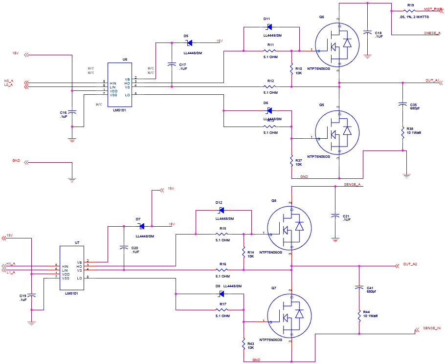
[Here is] a schematic for the motor driver portion of the design. It uses NTP75N06 FETs--They are available at digikey and are certainly overkill for what you want to do, but they are good for demonstration purposes, they are good to 60 Volts and can handle 75 Amps with only 10 milliohms of on resistance. They have our built in fly-back diode.
[It] drives one phase of the bipolar motor. You will need two pages like this. The inputs are a TTL signal to turn on each of the four FETs, a 15 Volt supply input for the charge pump and the motor drive voltage of say 50Volts. The outputs are the two that attach to the motor coil and finally a sense voltage out. It is attached to the high side so I can use a high side current sense chip.

Questions:
Hi, I have been looking for something like this. You mention current-sensing chips, what parts or type of parts are you thinking of? a search turns up nothing+
Interested:
David A Cary Says: " See also the LiniStepper " James Newton replies: Although the LiniStepper is Unipolar only, not Bi-Polar.+
| file: /Techref/io/stepper/hipwrbp-gm.htm, 5KB, , updated: 2008/8/12 09:05, local time: 2025/10/9 19:49,
216.73.216.137,10-3-124-149:LOG IN
|
| ©2025 These pages are served without commercial sponsorship. (No popup ads, etc...).Bandwidth abuse increases hosting cost forcing sponsorship or shutdown. This server aggressively defends against automated copying for any reason including offline viewing, duplication, etc... Please respect this requirement and DO NOT RIP THIS SITE. Questions? <A HREF="http://techref.massmind.org/techref/io/stepper/hipwrbp-gm.htm"> Design of a High Current Bipolar Stepper Motor Driver</A> |
| Did you find what you needed? |
Welcome to massmind.org! |
|
The Backwoods Guide to Computer Lingo |
.