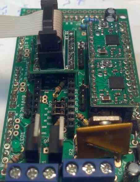


This cable / kit adapts the standard stepper driver connector on a RAMPs^ board (the Pololu driver) or other motion control board that normally uses Pololu drivers to the open source PMinMO standard so you can use any number of open source stepper motor drivers^. The THB6064AH driver is known to work with RAMPS / Marlin controllers.


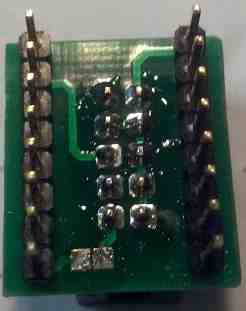
Assembly: First install the box header on the side of the PCB with the silkscreen, paying attention to the notch plastic notch that shows alignment. Note: On the new purple PCB, the square pad is NOT pin 1 of the box header. Pin one is near the "En". Then solder the headers on the outside. It helps to put them in the Pololu header first, so they are held straight up and down.
ENABLE: The square pads on the bottom of the PCB which are separated by a narrow gap, so that the enable signal is not passed on to the driver. Bridging these pads with solder will cause the enable signal from the RAMPs board to be fed into the driver.
When using the adapter with the BOB PID, you should bridge these pads so that the RAMPS enable signal is transmitted to the controller and on to the motor driver.
However, the default polarity of the enable signal for the THB6064AH driver driver is the opposite of that for the standard Pololu boards. As a result, the motors will lock when not moving, and release, failing to move, when the RAMPs system tries to move them. The enable signal is not required on the THB6064AH driver because it is enabled by default, and automatically goes into a low power hold when not in motion. If you do wish to make use of the enable line, with this driver you will need to change the polarity in the firmware. For other drivers, you can bridge the gap.
For Marlin, change the X, Y, Z or E _ENABLE_ON from 0 to 1 in the Configuration.h file
// For Inverting Stepper Enable Pins (Active Low) use 0, Non Inverting (Active High) use 1
// :{0:'Low',1:'High'}
#define X_ENABLE_ON 1
#define Y_ENABLE_ON 1
#define Z_ENABLE_ON 1
#define E_ENABLE_ON 1 // For all extruders
Note: Motor power is not connected because at the power levels our drivers manage, the pins on the RAMPS driver socket would melt. Motor power will need to be connected directly to our driver as specified in the driver documentation. +
RAMPS JP4:
Pin Signal - PMinMO Pin
 1. DIR    - 3
 2. STEP   - 5
 3. /SLP   - n/a
 4. /RST   - n/a
 5. MS3    - n/a
 6. MS2    - n/a
 7. MS1    - n/a
 8. /EN    - n/a (can be jumpered to 1)

RAMPS JP2:
Pin Signal - PMinMO Pin
 1. GND    - 7,2,4,6,8,10
 2. VDD    - 9
Note: Pin 1 on each side is at the bottom edge, opposite the alignment mark on the RAMPs board.
See also:
Questions:
This adapter cable is recommended for use with your BOB PID Servo Motor Control board controlling your DRV8701s DC motor driver. Since the DRV8701s needs the enable pin pulled high for operation do I need to solder across the pads on the bottom of this PMinMO adapter cable to feed the enable signal to the BOB PID?
Also, what version of Grbl was used in this? Do I need any changes within Grbl from the default settings? I'm currently trying to get things working with Grbl 1.1
James Newton of MassMind replies: Yes, you should enable connection of the enable signal by bridging that pad. I've updated the docs to indicate that. Any version of Grbl should work, as they all control stepper motors.+
| file: /Techref/io/stepper/PMinMOtoRAMPS.htm, 6KB, , updated: 2019/8/19 15:27, local time: 2025/10/16 11:11,
216.73.216.53,10-2-207-162:LOG IN
|
| ©2025 These pages are served without commercial sponsorship. (No popup ads, etc...).Bandwidth abuse increases hosting cost forcing sponsorship or shutdown. This server aggressively defends against automated copying for any reason including offline viewing, duplication, etc... Please respect this requirement and DO NOT RIP THIS SITE. Questions? <A HREF="http://techref.massmind.org/techref/io/stepper/PMinMOtoRAMPS.htm"> RAMPS, PMinMO, Open source, Stepper Motor, Stepper motor driver, 3DPrinter, Adapter Cable</A> |
| Did you find what you needed? |
Welcome to massmind.org! |
Welcome to techref.massmind.org! |
.