RLC-2: RS232 Level Converter for ECS in a DB9
backshell
Disclamers
*WARNING* CRT Monitors have a case for a reason: The
circuitry inside produces VERY high voltages which will KILL YOU DEAD if
you don't know what you are doing. If you have to open the case to get to
the ECS port on your monitor... don't.
We don't know anything about repairing monitors or about the DAS software.
We are just supplying a cable, built to the specifications provided on the
forum.
Cable
The pin order on the TTL connector is easy to change. Just press down on
the little locking pin through the slot in the plastic, and first push in,
then pull out the connector by the wire. This page has a nice explanation
with pictures:
http://www.marvin3m.com/connect/#remove
(cached)
SONY: The RLC-2 is the SONY ECS version of the
RLC-1. The RLC-1 can be turned into an ECS converter
just by swapping pins 1 and 2 in the connector. The pins on the TTL end of
the RLC-2 are already correct for the SONY ECS port. The pinout of the connector
on the RLC-2 is, from top to
bottom^:
Pin
Color
Signal
Description
1.
Black
GND
Connects to pin 1. GND on the Monitors ECS port
2.
White
+5V
Connects to pin 2. STBY +5VDC on the Monitors ECS port
3.
Yellow
Tx/Dout
Driven by the Monitor to send data to the PC (connects to pin 3.
"RX" on the Monitors ECS port
4.
Red
Rx/Din
Driven by the PC/RLC to send data to the Monitor (connects to pin 4.
"TX" on the Monitors ECS port
5.
Blue
RTS
unused, may need to be shorted to CTS depending on your PC and the software
used.
6.
Green
CTS
unused, may need to be shorted to RTS depending on your PC and the software
used.
PANASONIC: The RLC-2 must be modified by swapping the 1st and 2nd,
as well as the 3rd and 4th pins in the socket to match those on a Panasonic
monitor. The pinout of the connector on Panasonic monitors is, from top to
bottom:
Pin
Color
Signal
Description
1.
White
+5V
Connects to pin 1. STBY +5VDC on the Monitors ECS port
2.
Black
GND
Connects to pin 2. GND on the Monitors ECS port
3.
Red
Rx/Din
Driven by the PC/RLC to send data to the Monitor (connects to pin 3.
"TX" on the Monitors ECS port
4.
Yellow
Tx/Dout
Driven by the Monitor to send data to the PC (connects to pin 4.
"RX" on the Monitors ECS port
5.
Blue
RTS
unused, may need to be shorted to CTS depending on your PC and the software
used.
6.
Green
CTS
unused, may need to be shorted to RTS depending on your PC and the software
used.
(These pinouts are known to be correct for most supported monitors, but some
can be different . If you aren't sure of your monitor, use a meter to read
the voltage levels on the pins of the monitors ECS port and email those readings
to us with the monitor model)
HP: Brendan Hahn says "...for a D8915 chassis (HP p1120). I now have
black-white-red-yellow from pin 1; works great."
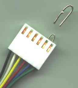
RTS/CTS: On some PC's the serial port may refuse to
send data until it recieves the CTS signal. You can provide this by connecting
pin 5 (blue wire) of the RLC connector to pin 6 (green wire) with a little
bit of bare wire bent into a jumper:
The RLC-2 RS232 to 3-Volt or 5-Volt (CMOS/TTL) Level converter provides
a simple, low-cost and easy to use solution to interfacing a CMOS or TTL
based circuit to an RS232/EIA232 serial port.
The RLC-2 contains an internal circuit to provide the positive and negative
voltages needed for true RS232/EIA232 compatibility and to convert these
voltages back to logic levels.
It is particularly suited to monitor adjustment applications; for SONY type
monitors.
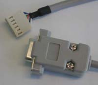
The RLC-2 is built into a small DB9 backshell with an 11" lead terminating
in a standard 0.1" (2.54mm) Molex KK-series 6 pin connector. The connector
is used to provide power to the converter and deliver the Serial data signals
to the attached circuit.
Its small size and convenience make it ideal for prototype or one-off systems,
eliminating the need to design and debug extra level shifting circuits. It
is also useful for circuits that need periodic connection to a host like
dataloggers where a single converter can be used with many products, reducing
the parts count and therefore cost for the individual units.
Connections
Logic Level Pin Assignments
Pin
Color
Signal
Description
1
BLK
Gnd
Ground Connection (0V).
2
WHT
Vcc
Power supply to the RLC-1. 3 to 5 Volts.
3
YEL
Data Out (TX)
Data sent from the logic level device to the RS232 device.
4
RED
Data In (RX)
Data sent from the RS232 device to the logic level device.
5
BLU
RTS
Request to Send signal sent from the RS232 device to the
logic level device to indicate it wishes to transmit data. This signal is
Active Low.
6
GRN
CTS
Clear to Send signal sent from the logic level device to
the RS232 device indicating that it can begin sending data. This signal is
Active Low.
Logic Level Interface
The logic level (CMOS and TTL compatible) interface is a Molex KK Series,
locking and polarised 6 pin crimp terminal housing. A compatible header for
these connectors should be available from most electronics stores, alternatively
a 0.1" (2.54mm) universal header could be used.
Note that the logic level interface is not isolated from the RS232 level
interface and they share a common Ground.
RS232 Interface
The RLC-2 is build into a DB9 Backshell and comes with a female DB9 connector.
The DB9 RS232 connector is wire as a standard "Null Modem"; DTR, DSR and
CD are permanently wired together but the RTS and CTS signals are provided
to the 5-Volt interface and must be connected together if not used in the
attached circuit.
Specifications
Symbol
Parameter
Conditions
Value
Unit
Min
Typ
Max
Isupply
Vcc Power Supply Current
No Load, TA = 25 Deg C
0.3
1
mA
VIL
Logic Level Input Threshold Low
0.8
V
VIH
Logic Level Input Threshold High
2
V
VOL
Logic Level Output Voltage Low
Iout = 1.6mA (to Vcc)
0.4
V
VOH
Logic Level Output Voltage High
Iout = 1mA (to Gnd)
Vcc-0.6
Vcc-0.1
V
DR
Data Rate
300
400
Kbps
Electrical Characteristics:
Vcc = 5V +/-10%, TA = -40 to 85 Deg C, unless otherwise
specified. Typical Values are referred to TA = 25 Deg C.
Absolute Maximum Ratings:
Absolute Maximum Ratings are those values beyond which damage to the device
may occur. Functional operation under these conditions is not to be implied.
Symbol
Parameter
Value
Unit
Notes
Vcc
Unit Power Supply
-0.3 to 6
V
Relative to Ground
VDout
Input Voltage on Data Out Connection
-0.3 to (Vcc +0.3)
V
Relative to Ground
VDin
Output Voltage on Data In Connection
-0.3 to (Vcc +0.3)
V
Relative to Ground
TStore
Storage Temperature Range
-55 to +125
°C
Options Available
Custom versions of this cable can be manufactured as needed. Note that
a minimum order quantity will apply for non-standard configurations. For
more information, please contact us.
The following are some of the available options: (all units now support 3
Volt as well as 5 Volt operation)
No Backshell
LED indicator lights for RX, TX, RTS and CTS.
Bare Leads for Logic Level Interface
Custom Connector for Logic Level Interface
RTS and CTS internally connected and a 4 Pin connector for the Logic Level
Interface
See also:
http://www.awce.com/rs1.htm Kit
with larger components. Does not include a cable, wrong pinout for ECS. 5
Volt operation only. As of 2006/08/03 the cost was $10 for the PCB only,
$14 for the kit and $26 A&T. If you don't mind the size and want to save
$5 in return for building the kit, this is a good option.
http://www.embedinc.com/products/ser
Larger, no case, no cable, wrong pinout for ECS, does not convert RTS or
DTS, does not support 3.3v. As of 2008/02/05 the price is one dollar less
up to qty 4, but the 5 unit price is $13.80 which is quite good.

 RTS/CTS: On some PC's the serial port may refuse to
send data until it recieves the CTS signal. You can provide this by connecting
pin 5 (blue wire) of the RLC connector to pin 6 (green wire) with a little
bit of bare wire bent into a jumper:
RTS/CTS: On some PC's the serial port may refuse to
send data until it recieves the CTS signal. You can provide this by connecting
pin 5 (blue wire) of the RLC connector to pin 6 (green wire) with a little
bit of bare wire bent into a jumper: