Low cost, high quality 1HP motor driver for brushed DC motors, ideal for use in closed loop servo systems.
This device is designed to control brushed DC motors up to 40 V and 18 A (720 Watts, 0.97 HP) continuous operation. It is ideal for adapting CNC machines such as routers, mills and 3D printers to Servo operation with low cost DC motors. It is pin compatible with the MassMind BOB PID Servo Control. It can also be used as the power stage of a mobile robot., DC-AC inverters, and for driving Peltier modules.
Open Loop Control: For basic open loop control, supply a PWM signal with a duty cycle for the desired speed to the PWM (aka STEP) pin and set the direction on DIR, while enabling the driver with a high value on ENB.
Closed Loop Control: A microcontroller, such as the ATmega328p (Arduino Uno, Arduino Nano, several other Arduino variants), should be present to read the e.g. STEP/DIR signals from the motion controller, read the position encoder e.g. quadrature and perform the calculations required for e.g. PID control of the motor position. The MassMind BOB PID Servo Control is a perfect fit.
| Parameter | Min | Typ | Max | Unit |
| Motor side voltage | 6 | 36 | 40 | V |
| Motor side continuous current | 18 | A | ||
| Logic side input voltage | 1.8 | 5 | V | |
| PWM frequency | 0 | 100 | kHz | |
| Duty cycle | 0 | 100 | % | |
| Current limit signal frequency | 10 | 100 | kHz | |
| Ambient temperature for operation | 0 | 40 | °C | |
| Weight | 0.85 (24) |
oz (g) |
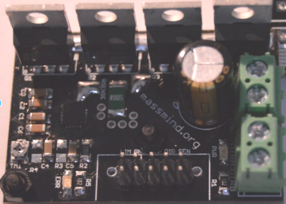
 MOSFET driver
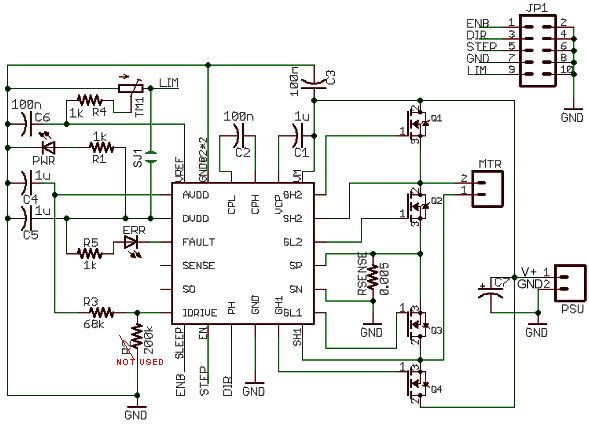
A DRV8701^ full bridge mosfet driver provides the capabilities to drive the MOSFET gates at an appropriate voltage with acceptable switching speed, while also protecting them from being damaged from heating due to insufficient gate voltage, shoot-through, etc.
It also controls an indicator LED for signaling the fault modes the device is able to detect, such as motor overcurrent and driver undervoltage.
Finally, the driver also performs a current limiting function to avoid damaging the transistors. The current level is set via a low pass filtered PWM signal or by a onboard trimpot.
Please note: Catch diodes, FET gate resistor, FET gate zener clamp diodes are NOT needed in this design. The internal diodes of the FETs are fast enough to catch any spikes, switching currents are set by one resistor on the board (not individual resistors for each FET), and the voltage clamps are provided with the gate driver.
The device utilizes four IRFB7546 MOSFETs. These transistors have a breakdown voltage of 60 V and a RDSon of 6.0 mOhm typically (a worst case resistance of 14.1 mOhm at 175 °C Tj) with a Vgs of 10 V.
Current limiting is accomplished by the driver by turning off the appropriate transistors by a voltage comparator sensing the voltage drop across RSENSE and comparing it to the voltage on LIM pin.
For setting the current limit using the onboard potentiometer one needs to measure the voltage between ground and the wiper pin. Then, one can calculate the current with the following expression:
I = 10[ohm-1] • Vpin - 0.5[A]
or
Vpin = (I + 0.5) / 10
For example, to get the maximum continuous current of 18 A, The wiper pin needs to measure 1.85 V. 18 + 0.5 = 18.5 then divide by 10 = 1.85
The current sensing resistor on the PCB reduces the current applied when the PCB temperature rises, preventing runaway and limiting max current when approaching the top end of capacity. In extreme cases, when extreme currents are applied, the resistor will act as a fuse, cracking and shutting down the unit, protecting the drivers.
| Connector | Pin | Signal | Description |
| JP1 -Bottom (all even pins are ground) |
1 | ENB | Enable |
| 3 | DIR | Direction | |
| 5 | PWM | PWM signal for motion | |
| 7 | GND | Ground pin for the board. | |
| 9 | 5V | Positive supply input for the board. PWM signal for off-board current limit |
This connector is a direct match for the output of the BOB PID Servo Controller.
1 Enable (nearest power / motor connector)
2 Direction
3 Ground
4 PWM
| Kit |
Part |
Qty |
Description |
 |
|||
| PCB | 1 | The printed circuit board and all surface mount components. Double sided, plated thru holes, professionally made. | |
| MTR | 1 | Power and motor screw terminal blocks: Phoenix Contact 1935776 rated 32 amps 13.5mm for up to 12 guage wire. (The more common smaller ones are 17 amps 11.3mm) | |
| PWR | 1 | ||
| C7 | 1 | 220 to 470uF axial through hole electrolytic capacitor. Long lead in the square pad | |
| Q1-4 | 4 | IRFB7546 MOSFETs. These must be thermally connected to a heatsink, but electrically isolated from one another. | |
| Mica | 4 | TO220 mica washer (taped to PCB) | |
| Washer | 4 | TO220 #4 shoulder washer. bushing/insulator | |
| Bolt | 4 | #4-40 bolt | |
| JP1 | 1 | Header 0.1" 2 x 5 PMinMO standard but DIR / STP(PWM) swapped. (or use a 0.2" spacing screw terminal) | |
1. [ ] Install JP1 shrouded header with the notch towards the inside of the board. (or install a 4 pin screw terminal in the same space)
2. [ ] Install MTR and PWR screw terminals.
3. [ ] Align the board with the heatsink and verify the position of mounting holes and the placement of Q1-4 MOSFETs. Mark, punch, drill, and tap holes for #4-40 bolts into the heatsink.
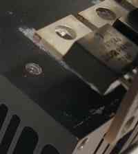
4. [ ] The power drivers will run across the back of the board, on 0.475" centers, about 0.25" from the back and with the first one centered at 0.280" from the left edge. The 4 power transistors Q1-Q4 MUST be insulated from the heatsink. This means the transistor bodies and metal tabs are NOT electrically connected to the heatsink.
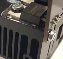
Use the clear Mica insulating washers, these go between the transistor body and the heatsink (see '1' in the diagram above). Use heatsink compound on both sides of the Mica washer, this only requires a tiny smear in the middle (which will squish flat when tightened down).
There is also a plastic insulator "shoulder washer" (see '2' in the diagram) this stops the metal screw touching the metal tab of the transistor. No heatsink compound is required on the screw.
After the transistors are mounted you should check them with a multi-meter (ohm meter or continuity tester) to make sure the transistor tab is NOT CONNECTED to the heatsink. Likewise the transistor tab should NOT be connected to the metal screw.
Once the mechanical mounting is done, solder the MOSFETs to the PCB.
5. [ ] Install C7 long lead in the square hole, and the stripe side towards the round hole. It can be installed all the way down on the PCB for physical stability, or bent over toward the RSENSE resistor, and secured with a bit of hot glue or double back foam.
Power: The device comes with two screw terminals. The one marked with the MOTOR-A and MOTOR-B labels should be connected to the two cables for powering your motor. The other terminal, marked V+ and V- should be connected to a power supply of the correct voltage, ensuring the correct polarity of the connection: Ground to V- and the positive supply to V+.
Terminal Block: An 0.2" spacing, 4 position terminal block
can be installed for the signal header as an option. In this case, the LIM
pin must be patched to ENB so the current limit is provided on board and
is adjusted via the trim pot or you can hort the SJ1 jumper (lower left corner
of the board, under the current adjust pot) to provide logic power to the
current limit (LIM) signal. The signals will be:
PMinMO 2x5 Header: This standard connector accepts signals from our BOB PID controller:
1. ENB the enable signal for the driver, active high. This is NOT the square pad, it's the opposite one. When the enable signal is present, the PWR LED will light (assuming the motor power supply is already powered). If the enable signal is not present, the PWR LED, and every MOSFET on the board will be turned off.3. DIR signals the direction of turn, forward or reverse.
5. PWM signals the motor to turn or stop, active high. PWM on this signal varies how hard the motor will try to turn. When in low state, the driver brakes the motor through the low side MOSFETs.
7. Ground (all even numbered pins are also ground)
9. LIM / +5 a current limit signal. This is the square pad on the PCB. On the standard PMinMO, this is +5, but the driver get's it's own logic power from motor power. The 5V applied to this pin will instead be use with the onboard trimpot for setting current limit. Or you can implement your own current control by providing your own voltage to this pin. It is possible to use a PWM signal to adjust the current limit, as a low pass filter is present on the board. You can also short the pads of SJ1 on the PCB to provide LIM from the onboard logic power; be aware this will back drive whatever you connect to pin 9 when the driver is enabled.
Note that the LED on the board will NOT light, and nothing will move,
even when motor power is applied, until the ENB (enable) signal is
high.
To avoid burning out a motor, adjust the onboard current limit system to provide no more power than the motor can manage. The voltage at the current limit test point near the should be set while the unit is running at full speed. Start with the desired maximum wattage and divide by your motor supply voltage to find maximum current. Then use that current to calculate the correct setting using this formula:
Vpin = (I + 0.5) / 10
For example, a 350 watt motor using a 35 volt supply should be limited to 10 Amps maximum current. 10 + 0.5 is 10.5, divided by 10 is 1.05, so the pot should be set to about 1 volt.
Hint: For anything over 10 amps, just set Vpin to the current divided by ten… it's close enough.
Be very careful to monitor the heat of the drivers for at least 20 minutes during normal operation. It can take time for heat to build up, and excess heat can fry the drivers. It's probably a good idea to monitor the motor as well.
See also:
Questions:
Comments:
| file: /Techref/io/motor/DRV8701s.htm, 21KB, , updated: 2021/5/1 10:48, local time: 2025/10/30 13:31,
216.73.216.50,10-8-63-169:LOG IN
|
| ©2025 These pages are served without commercial sponsorship. (No popup ads, etc...).Bandwidth abuse increases hosting cost forcing sponsorship or shutdown. This server aggressively defends against automated copying for any reason including offline viewing, duplication, etc... Please respect this requirement and DO NOT RIP THIS SITE. Questions? <A HREF="http://techref.massmind.org/techref/io/motor/DRV8701s.htm"> MassMind.org H-Bridge DC Motor Driver</A> |
| Did you find what you needed? |
Welcome to massmind.org! |
Welcome to techref.massmind.org! |
.