
 Case Case
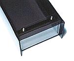
I used an acrylic board with transparent color for the bottom and used a brown color for the cover.
You can jump to the page of the making of the case when you click the photograph on the left.
Variable resistor / Knob
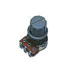
This variable resistor is used to set an alarm detection distance.
Sound horn
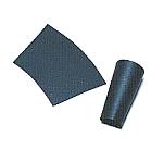
I put the sound horn with the 5-cm length to make the ultrasonic have the directivity.
This horn is put for the decrease of the ultrasonic which was reflected at the thing except the measurement object and for the prevention from transmission pulse's entering the receiver sensor.
I rolled up and made the paper. The color is OK as well as the black, too.
Back panel

I put the panel which wrote the name at the back.
It is the one which was printed in the color to the OHP sheet.
I put in the white paper for the letter be able to be clearly seen.
Light-emitting diode ( LED )
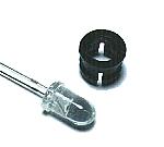
I used the red high brightness type with the 5-mm diameter. The plastic installation part is used to install in the case.
Output terminal

This is the terminal to output the result which detected an obstacle outside.
The point of contact (voltageless) of the relay is output.
Power supply connector
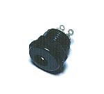
This is the connector to connect the AC adapter.
AC adapter
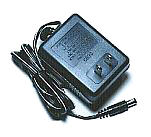
This is the power supply adapter to get DC +12V from AC 100V. The 300-mA electric current can be passed.
Ground board
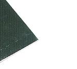
To strengthen the ground of the printed board which was separated to the two sheets, I installed the printed board on the brass with the 0.5-mm thickness.
Leg
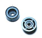
This is the leg to have put to the part in the bottom.
These legs are to protect the case when putting the measurement equipment.
Terminal cover
This is the cover which protects the connection part of the wiring.
Because the connection part is the circuit inside, it isn't touched. I used because I looked pleasant.
|