Manufacturing process
for the stabilised power unit
|
In case of the amateur, because there is not a special implement which manufactures the case, it is troubled. I introduce the power unit making process this time below. Because I used the implement which I have, I think that there is a way which is good for the others. I am glad if it becomes your reference. First, I make the hole which installs the part to the case.  The work preparation The work preparation
The protection sheet
Making the hole of the front panel I used the front panel sheet(One which was printed to the paper with the printer) for the positioning of the hole of the front panel. I print the sheet which deleted the red line which shows the outline of the part and fixe on the front panel with the tape. This sheet is the same as the design of the sheet to use for the complete equipment but at first, it is used for the hole making. Because it has made the hole, I print once again the sheet to use for the complete equipment. I put the mark to the position which makes the hole. In case of the complete case, the panel sometimes bends when using the punch. I put the mark by the pointed tool of the tip. It is possible to open out beautifully when changing into the gradually thick drill from the 3-mm hole and making the big hole. As for the hole which is bigger than 6 mm, I use the reamer. If approaching the size for the hole, I attempt to install the part and confirm the size of the hole. 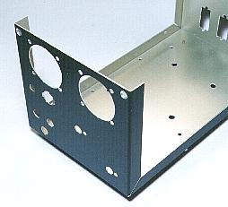 Because the hole of the meter has the 38-mm diameter, I use the thread saw. I write the circle of 38 mm of the directness on the front panel using the compass. I make a 3-mm hole inside a little of this circle and I passe the blade of the thread saw there. Then, I cut according to the circle. The hole after open removes the burr with the file and arranges the form. Then, I install the meter and adjust the size of the hole with the file. The installation hole of the LED which was used this time is the special form. I shave the unnecessary part of the hole with the file. Making the hole of the front panel acrylic sheet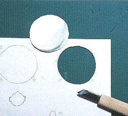 I make the hole of the acrylic sheet to fix the front panel sheet. I pile the acrylic sheet on the front panel and picture the cutting-off line along the hole. Because the paper sheet was set up to the acrylic sheet which I used, I pictured the line with the pencil. After that, I make the hole according to the line. I used the acrylic sheet with the 0.5-mm thickness. The cutter knife can not cut well. I used the graver. Making the hole of the front panel sheetI print the sheet to use for the complete equipment. I use the cutter knife and cut off the part of the hole according to the cutting-off line. I think that the hole of the actual front panel is different from the planned position little. If not mainly shifted, there is no problem. Because the sheet is the paper, the part which hits the component is bent, and the crack part which isn't fitted to the hole can be mumbling with the component and can not be seen. Making the hole of the rear panelThe AC cord, the fuse, the AC outlet are installed at the rear panel. I am not using the sheet like the front panel for the rear panel. Because it is, I picture the mark of the hole directly at the panel. I picture the position of the hole using the tool which was pointed to the protection sheet. 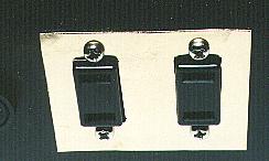 I made a mistake in the size of the AC outlet with the manufacture this time and had made a big hole. I decided to cover with another board. I made the hole which suits the AC outlet in the brass board of 0.5 mm and installed it at the rear panel. The aluminum board is OK. The one of the aluminum is easy to manufacture. The reinforcement of the front panel and the rear panel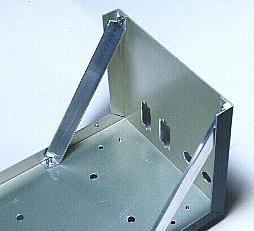 The case which was used this time composes the front panel, the rear panel, the bottom board with one sheet of the aluminum boards. There is not a support at the top of the front panel and the rear panel. I reinforced the top with the L-type aluminum stick. The fixation position is made to be able to be adjusted by making the hole of the oval at the bottom board. I adjust the angle of the panel so as not to bump when putting the lid to the case. I used the plate screw for the connection with the front panel. By using the plate screw, this screw hides under the front panel sheet and becomes that it isn't possible to be seen. The inner installation partI decide the position of the transformer, the regulator first. Because the weight of the transformer is heavy, it installs in the center of the case as much as possible. I rather installed in the back side in the relation of the space of the installation of the regulator. Because the meter and so on are put to the front panel, the center of gravity becomes the center approximately at the case. When having the handle of the lid, it is the good balance. I install the rectifier and the lug terminal on the bottom board in addition to the transformer and the regulator. Because the rectifier generates the heat, I install it on the case directly. These are either of the small parts. The part doesn't touch each other and I install in the place which can do the wiring easily. The ventilating hole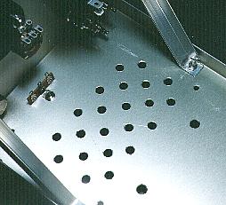 There are slits at the side of the case. Because the heat goes out from the regulator, the transformer and so on, I make the holes for the ventilation at the bottom board. 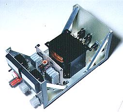 I attempted to install all parts in the fixed position to confirm the whole balance. 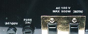 Because there are few numbers of the letters to display at the rear panel, I decided to use the lettering sheet. I used the adhesion film seal for the fixation of the seal. Because the part must be removed to stick the seal, I stick it before wiring. It is necessary to be careful for the air not to be included between the sheet and the panel when sticking the seal. Stick carefully from the end. I sticked the seal to the whole rear panel but it is OK only with the part of the letter. The air is included easily when the area which sticks the seal is wide and the work is terrible. Generally, the red for the positive voltage, the black, the white or the blue for the negative voltage is used. The yellow or the white is used for the signal line. At the electric circuit, the green is used for the grounding. There is a color standard to use for the wire. However, when using personally, it is OK even if it doesn't meet the standard. It is OK if you don't make a mistake. This time, I used the red for the positive voltage, the white for the negative voltage and the black for the grounding. When using the terminal cover, the cover must be passed through the wire before wiring. The wiring on the side of the front panel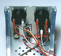 When wiring the part which is installed on the front panel, to facilitate the wiring work, the transformer and the regulator are removed once. I cut the wire to have put to the part of the front panel, containing the leeway and being long. I consider the length of the wire which can do the check by removing the printed board of the regulator. The route of the wiring must be decided in this step. Few electric currents which flow through this wire occur. Then, it is OK with the thin wire. Few electric currents which flow through this wire occur too. Then, it is OK with the thin wire. This time, I used the thick wire in the relation of the crimp-style terminal to put to the output terminal. 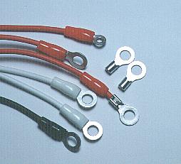 The about 5-A electric current flows through this wire. Then, I use the thick wire. Because the ammeter is put in the positive output circuit, the red wire is used. The ammeter has the positive terminal(The side which the electric current flows into) and the negative terminal(The side where the electric current pours). When connecting oppositely, the ammeter breaks. When making the color of the wire the same, it is necessary to be careful so as not to make a mistake in the positive and the negative. I used the crimp-style terminal for the wiring of the ammeter and the output terminal. Because the place of the installation of the output terminal is narrow, I can wire easily when using the crimp-style terminal. The crimp-style terminal press is used for the connection of the crimp-style terminal. The grounding connects with the case. I used the earth terminal of the lug terminal of the external resistor for the indicating lamp. The electric current which flows through this wire is about 16 mA. Then, it is OK with the thin wire. Because the LED has the positive terminal and the negative terminal, you make not make a mistake. Few electric currents which flow through this wire occur but the voltage is high. Then, I used the a little thick wire. The wiring on the side of the rear panel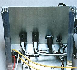 It is done in the removed condition in the transformer and the regulator when wiring the part which is installed on the rear panel, too. I wire the input wiring of AC 100V, the fuse, the AC outlets. The wiring to the transformer is made the length to have considered the leeway. The wiring for the inner installation partsThe wiring of the transformer, the regulator and the rectifier is done last. The wiring of the rectifier is done before fixing the transformer. I wire earlier in primary side before fixing the transformer. The wiring becomes difficult when fixing the transformer because the terminal on the primary side is below. The wiring of the secondary side is done after fixing the transformer. This is because it is easy for the one which fixed the transformer to confirm the route of the wiring. The input wiring, the output wiring and the voltage control wiring are done for the regulator. I confirm the wiring route of the condition to have fixed the regulator and the length of the wiring of the condition to have removed the regulator. The wiring is made as short in the condition that it is possible to remove the regulator. It was not in the first design but I installed the cement resistor to measure the efficiency. It is the cement resistor of 5 W. This was not in the first design too but I put to facilitate the voltage adjustment in case of the no-load. I connect this resistor with the terminal of the voltmeter. It is the cement resistor of 5 W.  I didn't assume this work at first. I found that the regulator surface temperature in case of the maximum output exceeded the allowable temperature (80°C) as a result of the thermometry. Because it was, I decided to install this fan. I didn't assume this work at first. I found that the regulator surface temperature in case of the maximum output exceeded the allowable temperature (80°C) as a result of the thermometry. Because it was, I decided to install this fan.I decided to install the fan on the rear panel of the equipment. Because a big hole must be made, the one is easier for you if you can plan from the beginning. I removed the transformer and the regulator once because I made a hole. Because it was necessary to be careful so as not for the bound waste to be included in the crack of the parts, it was quite terrible. The power supply of the fan connects with the primary side of the transformer in parallel. I blocked up the hole which is opened to the lid of the case to discharge the heat of the regulator efficiently out with the paper and the fresh air made enter only from the ventilating hole of the bottom board under the regulator. 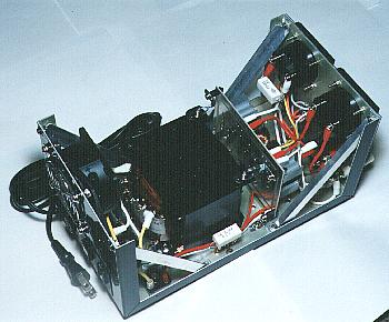 All wiring ended above. Confirm whether or not there is not a mistake sufficiently before turning on the power. |