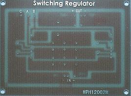
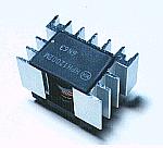
HPH12002M HPH12002M
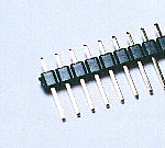
 |  | 1: | Input |
| 2: | Coil connection |
| 3: | GND |
| 4: | Coil connection |
| 5: | Output |
| 6: | Voltage adjust |
| 7: | Coil |
| Bottom view | 8: | Coil |
| Specification of HPH12002M |
| Rating input voltage | 32V | |
Input voltage
range | 24 - 40V |
Efficiency
(Vin=32V) | 85% Typ |
|
Switching
frequency | 35KHz |
| Rated output voltage | 12V |
| Output voltage precision | ±5% |
Input voltage change
(24 to 40V) | 15mV Typ |
|
Load change
(0 to 2A) | 100mV Typ |
| Temperature drift | ±1.7mV/°C |
| Output voltage variable range | 7 - 20V |
| Rated current | 2A |
| Ripple | 70mVp-p |
Over-current
protection |
Automatic return
hanging down operation |
|
Operation ambient
temperature |
-10 to
+80°C |
Low ESR capacitor
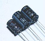
At the switching regulator, the big electric current flows through the capacitor. Therefore, it uses the capacitor of the small ESR(Equivalent Series Resistance) to prevent the generation of heat and the voltage drop.
Because the circuit this time outputs the 4-A electric current, I connect the capacitors of the low ESR in parallel and I make the ESR smaller.
Multilayer ceramic capacitor

Because the switching regulator switches over by the high frequency, the high frequency noise occurs. Because the high frequency characteristic is excellent, I am using the multilayer ceramic capacitor as the bypass capacitor of the high frequency. The bypass capacitor prevents high frequency noise's coming out to input and to output.
Chip-type resistor

This is the resistor to be using for the load balance of the regulator. This resistor is the surface mounting type which is directly soldered to the print pattern. I don't understand the permission electric power.(1W?)
The electric power to consume with this resistor with the circuit this time is 0.2 W(I2 x R = (2A)2 x 0.05ohm).
The size of the resistor has the 3-mm height, the 6-mm width, the 1.8-mm thickness.
Filtering coil

The power unit which was made this time can output the a maximum of 4-A electric current. Because it was, the coil to use for the filter circuit used the things for 5 A.
Because the coil with the size which I want could not be acquired, I made it by myself.
I rolled up the 1 mm thick PEW(Polyester enameled copper wire) around the core with 15 mm of the outside diameters, the 10-mm caliber, the 10-mm height the 22 times and I made the toroidal coil. After measuring the inductance, it was 25 µH.
When passing the big electric current, the core must use the big one too. The magnetic flux increases when the electric current increases. The magnetic flux is saturated when the core is small and the inductance decreases and the loss increases.
The big inductance value isn't needed by the circuit this time. I had priority over the mounting space and used the small core.
To make the toroidal coil with the thick wire with the small core, the power is necessary. I was troubled.
Printed board
I used the positive exposure printed board for the double sided of 100 mm x 75mm.
It is not necessary the double sided. I used in the purpose to put the name.
It is not the way with the good efficiency. It is my taste. It is enough in the single-sided printed board.
Wiring terminal
This is the terminal to connect the switching regulator and the outside part by the wiring.
The original use of this terminal is for the jumper.
Metallic stud

I use this to install the printed board to the case. There is not necessity of the metal.
I used the one with the 5-mm height for the 3-mm screw.
|