Parts explanation
for the infrared sensor
 I am using the Fresnel lens to extend the distance to detect with the infrared sensor. The about 30-m detection can be done with this lens. The eyesight angle of the lens which was used this time is the 2.5 degrees.   For the details of the Fresnel lens, refer to "Parts explanation supplement of the infrared sensor". 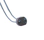 The Cds is the device which the resistance value changes by the strength of the shining. At the circuit this time, it is used to control the operation of the output circuit in the light around. 
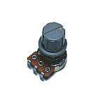 This is the variable resistor to adjust the operation level of the output circuit in the light around.  This is the terminal to output the result which detected the change of the infrared rays with the sensor outside. The point of contact (voltageless) of the relay is output.  This is the cover which protects the connection part of the wiring. Because the connection part is the circuit inside, it isn't touched. I used because I looked pleasant.  I put the panel which wrote the name at the back. It is the one which was printed in the color to the OHP sheet. I put in the white paper for the letter be able to be clearly seen. 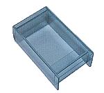 I made the case with the acrylic board. I considered the size of the Fresnel lens, the connector of the back and so on and I made the size the 125-mm length, the 70-mm width, the 50-mm height. I intended to use the acrylic board with the color for the cover. However, I used the glass color acrylic board because I put the Cds inside. You can jump to the page of the making of the case when you click the photograph on the left. 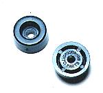 This is the leg to have put to the part in the bottom. These legs are to protect the case when putting the measurement equipment. 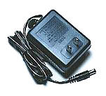 This is the power supply adapter to get DC +12V from AC 100V. The 300-mA electric current can be passed. 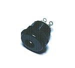 This is the connector to connect the AC adapter. There are some sizes in the plug of the AC adapter. The size of the connector and the plug must be fit. When there is not a connector which fitted the plug, cut off the plug and change into the plug which fitted the connector. The connection of the power supply must be careful so as not to make a mistake in the polarity with the voltage. |
||||||||||||||||||||