Parts explanation
for the infrared sensor unit
 This is the sensor to detect the change of the infrared rays. The infrared sensor which was used this time is the dual element type which is using the two elements. 
As for the operation of the sensor, refer to "Parts explanation supplement of the infrared sensor".  This is the IC that the four operational amplifiers are housed in the one package. It is possible to work with the single power supply. It is used for the signal amplifier and the window comparator circuit. LM324 can be used.  This is the precision timer IC. It is used to continue the output in the constant time.  This is the transistor with the general NPN type for the small signal amplification. It is used for the drive circuit of the relay. If the collector electric current is the equal to or more than 100-mA one with the general NPN-type transistor for the small signal, the other transistor is OK.  This is the IC to make the stable voltage of +5 V. The maximum input voltage is 30 V and can pass the about 100-mA electric current.  This is the switching diode for the small signal. The other one is OK.  This is the diode which shines when the electric current flows. It lights up when detecting the person or the animal.  This is the small relay which is made by the OMRON company. The drive voltage is DC 12V. This is the small relay which is made by the OMRON company. The drive voltage is DC 12V.The size has to do 10 mm of vertical, 15.6 mm of the sides, the 7.5-mm height. As for the specification of the point of contact, the voltage is to 60 V and the electric current is to 0.5 A in the AC and the DC. There is polarity in the coil of this relay. When connecting oppositely, the relay doesn't work. I found this thing when doing the performance test. Consider the drive voltage, the number of the points of contact, the point of contact permission voltage, the point of contact permissible current, the size and so on and choose the relay.  This is the socket to mount the IC. It is OK even if it solders the ICs directly to the printed board.  I used 1/4 W this time. The 1/8 W one is OK. 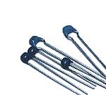 These capacitors are used as the capacitor of the integration circuit and the bypass capacitor of the power supply. At the circuit this time, because it doesn't handle the high frequency, it is OK even if it uses the film-type capacitors. 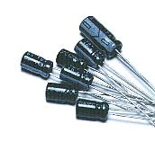 These capacitors are used as the coupling of the amplifier and the ripple filter of the power supply. Because there is polarity in the lead wire of this capacitor, be careful so as not to make a mistake when mounting. 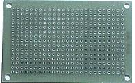 I used the universal printed board. It is the boad with 15 holes x 25 holes. 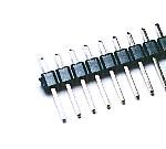 I used this terminal to connect the power supply wiring, the VR1 wiring and to put the infrared sensor and the Cds.  I used the type with the 10-mm length. The circuit this time is installing the cylindrical Fresnel lens in the infrared sensor. It adjusts the height of the printed board at the length of this stud for the lens to become the middle with the height of the case when setting the circuit in the case. |