Make the holes
[Menu]>[Manufacturing of Original PCB]>[The process of the PCB making]
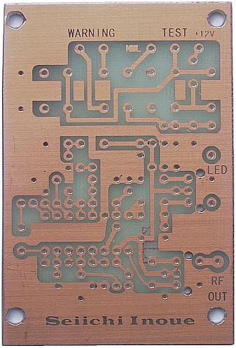 Make the holes which pass the lead line of the parts through the printed board. In case of the electronic parts of the resistors, the capacitors and so on, it uses the drill bit of the 0.6-mm. For the lead line of the case of the high frequency transformer, it uses the 1-mm drill bit. It is easily opened when using the electric mini drill to make a hole of 0.6 mm, 1.0 mm. As for the hole to fasten the printed board to the case and so on, it uses the 3.2-mm drill bit. Make the hole with the appropriate size in the size of each part, the screw kind. The hole to have opened with the drill becomes the condition that the perimeter is sharp(the burr). Use the bit of the a little big drill to remove this. In case of 0.6 mm, it is 2.5 mm. In case of 1.0 mm, it is 2.5 mm. In case of 3.2 mm, it is 6.0 mm. It is possible to remove if having the bit of the drill with the hand and doing it the 1-twice lightly. Usual printed board was complete with the work to here. |