
 Case Case

I made case with acrylic board.
You can jump to the page of making of case when you click the photograph on the left.
Variable resistor
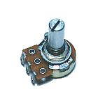
Propagation speed of the sound wave changes with the temperature.
This variable resistor is used to revise the error of the display by the change of the temperature.
Knob

This is the knob to have put to the variable resistor for the temperature revision. I used the small one.
Back panel
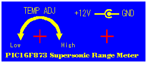
I put the panel which wrote the name at the back.
It is the one which was printed in the color to the OHP sheet.
I put in the white paper for the letter be able to be clearly seen.
AC adapter
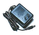
This is the power supply adapter to get DC +12V from AC 100V. The 300-mA electric current can be passed. Because the circuit this time is less than 100 mA, it is enough. It is the cheap one. So, I think that the inner circuit is composed of the small transformer, the rectifier and the simple ripple filter circuit.
The one that I resolved before became like this. The output voltage in case of the no-load was to +15V be.
At the expensive adapter, the switching regulator is used for the circuit inside. The output voltage of this type is stable.
Power supply connector
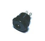
This is the connector to connect the AC adapter.
There are some sizes in the plug of the AC adapter. The size of the connector and the plug must be fit. When there is not a connector which fitted the plug, cut off the plug and change into the plug which fitted the connector.
The connection of the power supply must be careful so as not to make a mistake in the polarity with the voltage.
Terminal cover
This is the cover which protects the connection part of the wiring.
Because the connection part is the circuit inside, it isn't touched. I used because I looked pleasant.
LED display filter
This purple colored acrylic board is put for making LEDs display clear.
Purple colored acrylic board hides the segment where the LED doesn't light up and can display the lighting segment brightly.
At first, I planned to put this acrylic board to the case. However, the crack had built between the LED and the case. Therefore, I pasted acrylic board on the LED directly using the glue.
Ground board
I installed the printed board on the brass with the 0.5-mm thickness to strengthen the ground.
|