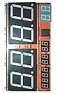
On these pages, I will introduce a circuit which arranged the contents introduced by the "Radio Controlled Clock". The changed part is a display circuit and is made easy to see using the large-size 7 segment LED. Moreover, an LED matrix is used for the display of a day of the week, and the display with a Japanese character(Kanji) is made to perform.
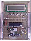
The almost same software as "Radio Controlled Clock" is used for clock control software. Reconstruction for outputting time information to a display is carried out. In "Radio Controlled Clock", PIC16F873 is used but the input-output port to output time information isn't enough. Therefore, I decided to use PIC16F877(40 pins).
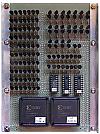
Latch registers are used to maintain time information for the display. I used D-FF of the 7-bit x 16 circuits on two CPLDs (XC9572-84) in order to make a circuit compact. This was created before for the other circuit.
PIC16F628 is used for the circuit which displays a day of the week by the kanji in the LED matrix. Also, an order lighting-up control is done to suppress the consumption electric power of the LED. PIC16F628 is used for this control, too. |