Parts explanation
of Light controller
 In this circuit, PIC16F873 is used. And compare feature and A/D converter feature are used.  This regulator is used to make the stable power of +5V. The maximum output current is 100 mA.  This transistor is used to drive MOS FET by the output of PIC. It is converting the output of PIC (0V to 5V) into the voltage to control an FET (0V to 12V).  This is P channel MOS FET. The maximum drain current is 30A. When the FET is in the ON condition, the resistance between drain and source is 25 milli-ohm. So, the electric power loss when the 10-A electric current flows in the ON condition is 2.5 W.  Because the ON resistance of 2SJ471 is 25 miliohms, the heat generation is not so big. The size of heat sink is the 25-mm height, the 23-mm width of the surface which installs the MOS FET and the 10-mm depth to the direction of fin.
I think that it is too big a little. 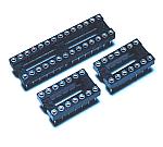 PIC16F873 is 28 pins of the slim type. When you can not get a slim-type 28 pin socket, two sockets of 14 pins can be used. In this circuit, I used two 14 pin sockets.  I used 10-MHz resonator. When changing the frequency of resonator, the value with all kinds on the software must be changed.  I used B type. 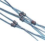 I used 1/8W as all resistors.  These capacitors are used to bypass the high frequency noise of the input and output of the power supply. 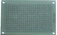 This is an universal printed board with 15 x 25 halls. 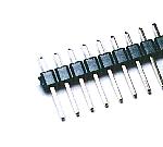 This terminal is used to connect a power supply wire and load. 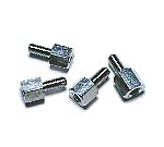 This is used as the leg of the printed board. |