Circuit explanation of signboard
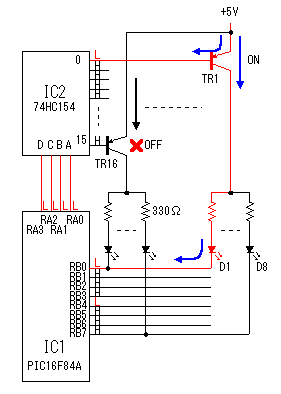
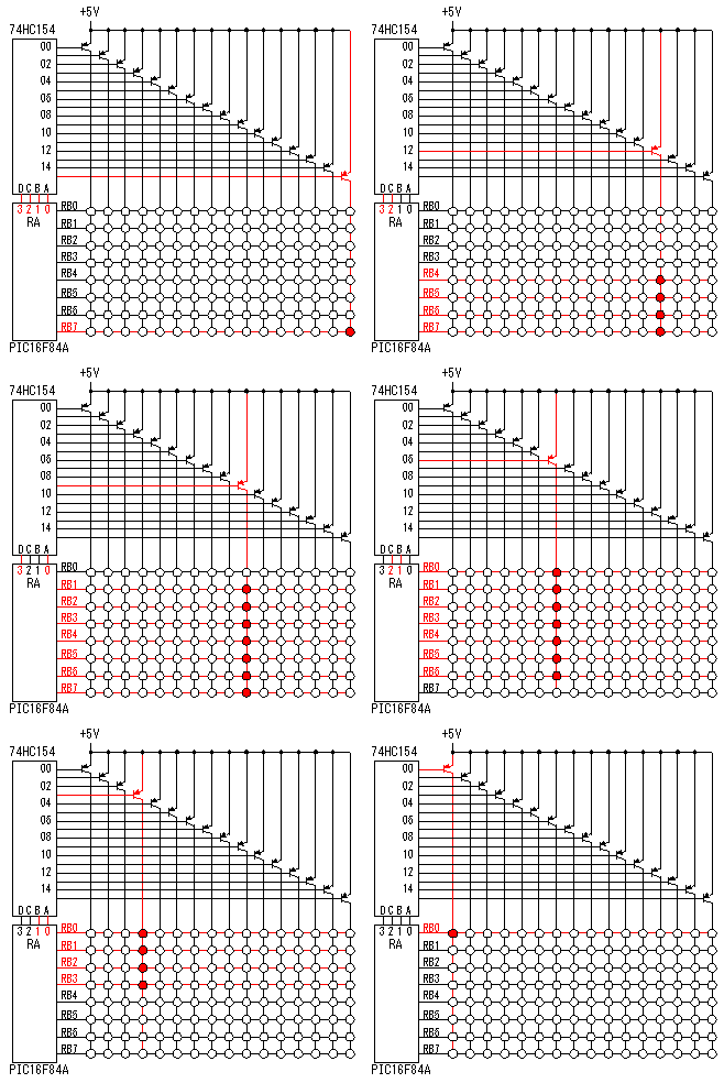
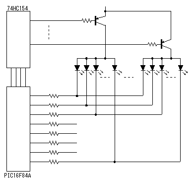
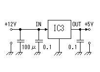
 RA3-RA0 ports are used for the signal output of the row that LEDs are controlled. RB7-RB0 ports are used for the output of the LED control signal of each row. 74HC154(4 to 16 Demultiplexer) is the IC which decodes the binary signal of 4 bits into 16 signals. As for the left figure, all RA ports are in the L level condition. In this case, only outout-0 of 74HC154 is L level. Then, only TR1 is in the ON condition, the other transistors are in the OFF condition. So, only the LEDs which are connected with TR1 are in the lighting-up possible condition. The lighting-up of the LED is decided in the condition of the RB7-RB0 ports. In case of the left figure, because RB0 and RB4 are L level, D1 and D5(It isn't displayed in figure) light up. The other LEDs are connected with RB0 and RB4 can't be lit up, because the transistors for the power supply to those LEDs are in the OFF condition.  The figure on the left shows the situation of the LED blink by the RA ports and the RB ports of PIC16F84A. You can find that the lighting-up time of one LED is 1/16 with this animation. If using latch registers for each LED row, the lighting-up time of the LEDs can be made long. I don't use latch registers because the printed board space needs more.  When I designed this circuit, I planed to use latch registers. Therefore, resistors for the current control are put in each LED. However, in the circuit which was made this time, because the LEDs of each row doesn't light up at the same time. So, it's OK to put the resistors only for one row in common.  This is the circuit which used 10-MHz resonator. It is very simple.  3 terminal regulator is used to get +5V output from +12V power in. There is possibility that a maximum of eight LEDs light up at the same time. The current in the case is about 90 mA. The 100 mA-type regulator can be used. However, I used a 1-A type for the safety. |