Parts explanation (1)
of 4 Channel Adapter for the Oscilloscope
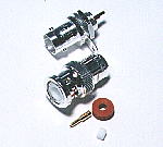 I used the BNC plug and receptacle as the connector for the input and output of the signal. This connector was a connector for the high frequency coaxial cable and used of 1.5C2V as the cable this time. The adapter which was made this time can handle only an about 100-kHz signal. Because it is, you can use a jack and a screened cable for the audio for the input/output of the signal. The connection between the BNC plug and the coaxial cable is troublesome a little. Because the way of connecting depends on the plug maker little, you see structure well and must connect it. Because the cap part depends on the kind of the coaxial cable (5C2V/3C2V/1.5C2V) about the BNC plug, you need an attention when you buy.  Structure of the BNC plug The name of each part is not a formal name with the one which I put selfishly. 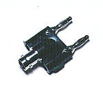 The input terminal of my oscilloscope is a banana plug. It should put a banana plug to the cable which connects with the adapter but one becomes apart in case of being a banana plug. Therefore, I used the plug which was shown with the photograph and decided to use a BNC plug. 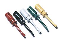 The electric signal to monitor with the oscilloscope is gotten from the lead line of the part of the electronic circuits and so on. When connecting a signal conductor, it is necessary for the attaching or removing to be easy, to be able to connect surely and not to contact a neighbor part. The "J" type lead line goes out of the tip when you push the part of the head of the plug with the finger and can hitch to the part. The lead line returns with the spring when separating a finger and puts in the lead line of the part tightly. 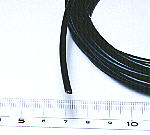 I used a coaxial cable as the signal input and output cable. At the frequency (about 100 KHz) which the adapter this time can handle, it is luxurious. You can use the screened cable for the audio, too. 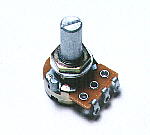 You can do a vertical positon adjustment and a mu factor adjustment of the input amplifier. The resistance value change type of the variable resistor uses "the B curve". As for the change curve, refer to the page of the resistors. 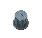 This is the knob to turn the axis of the variable resistor for the vertical position adjustment and the mu factor adjustment. Because the panel of the adapter was narrow, I used small one. The installation hole of the knob must be adjusted to the diameter of the axis of the variable resistor. Because the diameter of the axis depends on the kind of the variable resistor, you must ascertain when you buy. 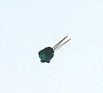 I put a light-emitting diode every input terminal. An adapter this time is switched to the 2 channel use and the 4 channel use in the input. They are to have the purpose of the pilot lamp of the adapter and the distinguishing of 2 channel use or 4 channel use. 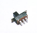 This switch switches a practicable input channel number. This switch switches a practicable input channel number.There are two sets of independent a-contact(make) and b-contact(break) in the slide switch which was used this time. The a-contact is the terminal which is connected with the common terminal when making a switch ON. The b-contact is the terminal which is detached from the common terminal when making a switch ON. The switch which has one set of a and b-contacts is called 3 P. It is because it has three terminals of the make terminal, the common terminal and the breakage terminal. Because there are six terminals, a switch of two sets is called 6 P. I am expressing in the explanation above with the case of ON but the distinction of ON/OFF is not in switch itself. For example, it is when OFF of the switch is a slide condition on the left, it is an a-contact that the terminal which connects with the common terminal doesn't connect by the b-contact. This switch is OK with the switch of the other type. Because I used a snap switch as the power supply switch, I considered that it made not mistake for the power supply switch. A square hole must be made in the installation of the slide switch. It is troublesome a little. It is simple because it is a circular hole in case of the snap switch. 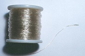 This is the wire of the vinyl to use to tie the cable. When strangling in this wire, the cable doesn't shift. Because it is, the curve of the cable can be fixed on the free form. |