Testing
|
The testing and also adjustment are important, after the electronic circuit device is made. When it is an easy circuit, the confirmation is easy. However, in the complicated circuit, sometimes there are loose soldering or adjustment are necessary and do not confirm right away. I will introduce the several instruments that test and also adjust the device that was completed. 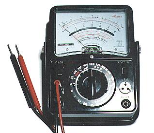 Circuit tester can measure various electric values. Such as the measurement of the resistor value, the measurement of the voltage, the measurement of the current, the confirmation of the polarity of the light emitting diode etc. This tool is necessary for electronic circuit making. Circuit tester can measure various electric values. Such as the measurement of the resistor value, the measurement of the voltage, the measurement of the current, the confirmation of the polarity of the light emitting diode etc. This tool is necessary for electronic circuit making.The circuit teser shown on photograph is an analog type, the measurement result is confirmed with the needle that calls the meter. Besides there is a digital type, the measurement result is confirmed with the digital display. Digital type can easily confirm the result. Even the analog type is able to use sufficiently. I am using and like the analog type. Fundamentally following items can measure by the circuit tester.
Some circuit tester can measure the value of capacitor, the value of coil, the characteristic of transistor etc. 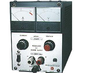 The electronic circuits which used a transistor, IC and so on can not be directly worked by AC100 V. Usually, those powers are from several V to tens of V in the direct current. Therefore the power supply unit becomes need to confirm the operation of the circuit that was completed. The power supply voltage differs by the circuit, then the power unit that the voltage is able to change is convenient for the power supply device.  The value of capacitor is displayed to the part body. But the display method may differ by supplier, as I mentioned in the page of the parts. The display sometimes closes disappear. Also, the tolerance of capacitance may be confirmed. The capacitance measuring device is convenient. It isn't always necessary to do this tool. 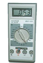 This is the measuring device called a LCR meter. This device can mesure the value of coil(L), capacitor(C) and resistor(R) each. Measurement range is shown below ( incase of right photograph )
The photograph of the right is measuring the coil of 56 micro H(µH) with the 2 mH range. It is displayed as 53 µH. This is convenient for circuit making. 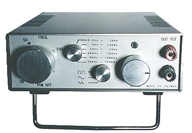 When confirming the electronic circuits in the operation, it is sometimes necessary to input the signal from outside. The photograph thing is called a function generator and can produce rectangle wave, sine wave, triangular wave. Frequency is able to oscilate from 0.5Hz to 300KHz. The measurement accuracy must be paid attention in the case of the hand-made measuring device. If there are many errors of a measuring device, the measurement result does not have the meaning. This measuring device is adjusted with the normal frequency counter, then it is able to use be sufficient to do the confirmation of the circuit that I make. 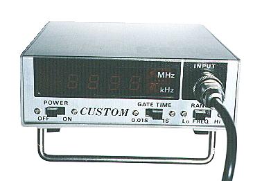 This is the tool that confirm the oscillation frequency. The frequency from 5Hz to 50MHz can be measured. 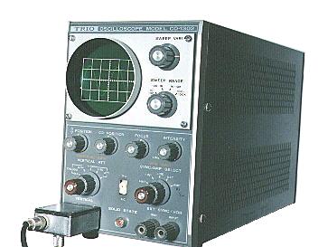 This tool is used to observe the waveform of voltage. The oscillo scope whitch is shown on photograph is a very old one, I think that you can find it in the museum or junk shop probably. Now the wonderful measuring device is sold. In my case, this oscillo is useful to check the waveform of the voltage. You who have this tool are a specialist. 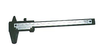 This tool can measure the size with the unit 1/10 mm. 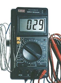 This is the measurement receptacle which displays the voltage, the electric current, the other measurement result in the digital. The display is easy to see compared with the analog-type circuit tester and the contents which can be measured are very rich. The digital type always needs the battery but in case of the analog-type circuit tester, it is possible to measure without the battery except the measurement of the resistance. Recently, the digital type is oftener used. I am using the analog type mainly. The wire which is connected with the left yellow connector of the tester is the probe of the thermocouple thermometry. The tip of the wire has the thermocouple temperature sensor. The one of the photograph chooses the measurement item with the switch in the 32 positions. Following measurement is possible.
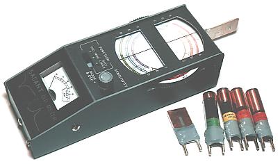 The dip meter is the equipment which measures the frequency of the resonance circuit. There is an oscillation circuit in the meter and the oscillation energy can be confirmed with the meter. In case of the measurement receptacle of the photograph on the left, the coil of the oscillation circuit is mounted on the socket of the case. The range to measure can be changed by changing a coil. A way of measuring is shown below. Bring the coil of the dip meter close to the coil with the measured resonance circuit. Turn the dial of the dip meter and change an oscillation frequency little by little. When becoming a resonant frequency, the oscillation energy of the dip meter is sucked up by the measured resonance circuit and the needle of the meter dips. So, this is called DIP meter. The dip meter has the other way of using in addition to measuring a resonant frequency. The oscillation frequency of the circuit can be measured. Stop the oscillation circuit of the dip meter and bring the coil of the dip meter close to the circuit to be oscillating and turn a dial. When becoming an oscillation frequency, the needle of the meter rises. With this, you can recognize the oscillation frequency of the circuit. And it is possible to use as the simple oscillator. Dip meter oscillates at the frequency which is shown by the dial. So, it is possible to use for the adjustment of the receiver. The tuning circuit with receiver can be adjusted by making oscillate the dip meter at the frequency to desire. Also, when not finding a tuning frequency with receiver, it is possible to find with the dip meter. This meter can not recognize a detailed frequency like the frequency counter. In case of the dip meter to be introducing here, it is possible to do the measurement of following frequency by changing coils.
|
|||||||||||||||||||||||||||||||||||||||||||||||||||||||||||||||||||||||||||||||||||||||||||||||||||||||||||||||||||||||||