Parts explanation for Count-down timer
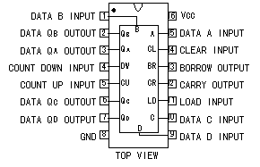 It is using for the counter in the minute and the second. This counter can be used for either of the count-up and the count-down. This time, it is doing the way of using the count-down exclusive use. 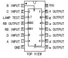 This is the IC which changes from the figure information which is shown with the BCD(Binary Coded Decimal) into the digital display of the 7 segment LED. Because the grounding part becomes common, the LED must use the anode common type. 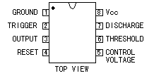 This is the oscillator to make the 1-Hz clock signal. 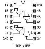 This is the NAND gate where there are two input terminals. The four gate circuits are housed in the one package. Only when the two input terminals are the High level (+5V), the output becomes the Low level (0V). 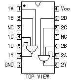 This is the NAND gate where there are four input terminals. The two gate circuits are housed in the one package. The output becomes the L level only when all four input terminals are the H level. 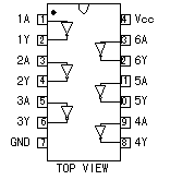 This is the inverter which outputs the condition contrary to the input. The six gate circuits are housed in the one package. 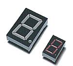 This is the LED in the 7 segments which display the minute and the second. This is the LED in the 7 segments which display the minute and the second.I used the a little biggish one for the minute display. For the minute display, it is SL-8139 which is made by the SANYO and for the second display, it is the name SL-1199. Each size is shown below.
For the second display : 18.8mm(H) x 12mm(W) x 8mm(D) 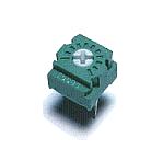 This is the variable resistor which adjusts the clock frequency to do the count-down. This is the variable resistor which adjusts the clock frequency to do the count-down.The frequency becomes high when turning clockwise. (The count down time becomes short) The measured result is shown below.
(Full turn to the left) 0 k-ohm : 1.13Hz(68 pulses/minute) (Full turn to the right)
(Full turn to the left) 0 k-ohm : 87 minutes (-13%) (Full turn to the right) As for the resistance value, in the smaller one, the adjustment range becomes narrower and the adjustment is easy.(It is easy to adjust correctly). However, it is necessary to make it be possible to set to the 1 second in the adjustment range. The obtaining of the fixed resistance (R4) is difficult. 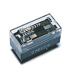 It closes the voltageless point of contact while the timer works to control the equipment outside. Because the relay is small, the electric current which can pour into the point of contact isn't so big.(Hundreds mA?) Because it is, you must prepare the relay which is appropriate to the outside to control the equipment which needs the big electric current.  With the rapid change when the electric current of the coil of the relay flows or broken, the high voltage occurs to the coil. This diode is put to protect the transistor from the voltage. Even if it doesn't put, the transistor doesn't break immediately. 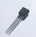 This is the thing to drive the relay by the output of the NAND gate. It may are not 2SC1815. I used because there was this at hand. 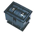 This is the BCD switch to set in the minute. The switch is the thin cylinder and can see the setting figure from the front. The circular cylinder has the small nail. You can set it by raising and lowering it with the finger. The one which I used this time is made by the JAE company. It is composed of following components. You can use the necessary components by combining. This time, it is the 2-digit composition but you can compose the switch of a lot of digits by combining them. 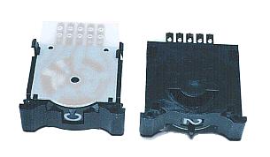
The size in this case is 24mm(H) x 33mm(W) x 30mm(D). 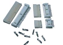 The control unit and the display unit of the timer are separated. It connects the interval of it with the cable. It is convenient for the maintenance when installing the connector in the side of the cable. This time, it made the side of the control unit connect with the connector. The control unit and the display unit of the timer are separated. It connects the interval of it with the cable. It is convenient for the maintenance when installing the connector in the side of the cable. This time, it made the side of the control unit connect with the connector.
For the BCD switch : 10 pins For the power supply : 5 pins 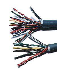 I used the numerous strand screened cable for the connection between the control unit and the display unit and the connection between the control unit and the BCD switch. I used the numerous strand screened cable for the connection between the control unit and the display unit and the connection between the control unit and the BCD switch.
For the BCD switch : 10 wires I protected the end of the cable with the tube(Type which shrinks when applying heat). 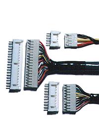 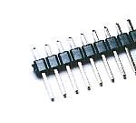 It is using to connect the power supply line, the start switch and the relay output. Because the about 40 pins are connected, you cut and use the necessary number. 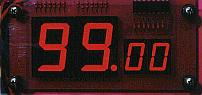 You can see the figure by the clearance when you see the LED through the purple acrylic sheet. It becomes beautiful like the design, too, because the body of the LED doesn't seem to be direct. 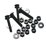 The display unit is installed in the hole of the case of the equipment which installs the timer. First, you put the acrylic sheet outside the case and fix the acrylic sheet on the case with the installation screw and the nut. Next, you install the display unit with the installation screw from inside the case. You adjust the interval of the unit and the case in the position of the nut. 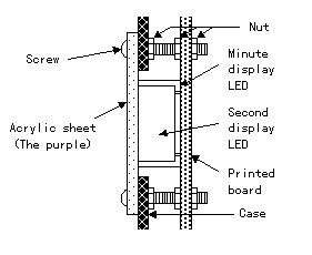 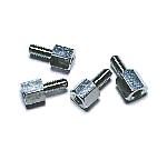 It uses to install the printed board to the case. It is OK rather than the one which is made from the metal, too. It doesn't care in the plastic one. 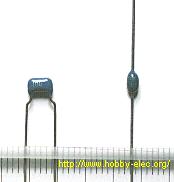 The digital circuit handles the square wave. As for the square wave, like the frequency, the high frequency component is contained. The voltage changes rapidly for the high frequency component to be contained. The high frequency component sometimes has an influence which is bad for the circuit to work. Because it is, the capacitor with the good high frequency characteristic can be put to the power circuit to lead the high frequency component to the ground (the 0-V potential). The ceramic capacitor |