
 Installation of heat sink Installation of heat sink
 |
In case of installation of the FET to the heat sink, I decided an installation position, considering a calorific value. The ON resistance of 2SJ471 is 25 miliohms and the ON resistance of 2SK2956 is 7 miliohms. So, when the same electric current flows, in 2SJ471, about 4 times of heat occur compared with 2SK2956.
Therefore, I put 2SJ471 which a lot of heat occurs to the upper side of the heat sink and allocate the area which is wider than 2SK2956 for radiation. Because the heat rises up, the FETs are put to the a little low position. |
|
I paint silicon grease FETs to make it easy for the heat of the FETs to spread through the heat sink.
Because both 2SJ471 and 2SK2956 are mold type, it does not need to use silicon rubber for the insulation. |  |
|
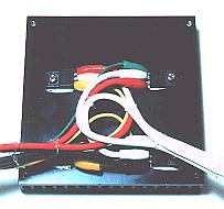 | Because the wiring materials are thick, I tie the wiring materials with the string of the vinyl so as not for the load to hang over the lead wire of FETs. |
|  |
|
Hole making of the case
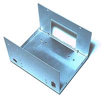 | It makes a square hole for FETs with installation to the heat sink to be stored inside the case. Making the female screw of 3 mm at the heat sink for the installation to the FET and the case, using a tap. |
Supporter for the input cable fixation
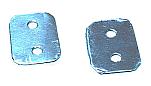 | I decided to tie the input cable of DC12V with cord binder when not using the inverter. I used an aluminum plate with 0.5-mm thickness to fix a cord binder on the case. Because the cord binder is cloth, it isn't possible to be fixed when not using a supporter. |
Installation of the control unit
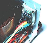 | Because it was full almost when a transformer was put to the case which was used this time, I put control unit to the front panel. |
Wiring on the side of the input
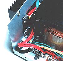 |
Careful work was needed so as not for the soldering iron to touch the vinyl wire because the wire was thick and the place was narrow.
I used a 80-W soldering iron. The small soldering iron can not solder a thick wire. |
Wiring on the side of the output
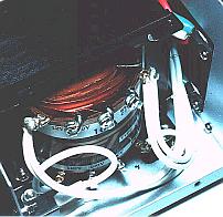 | I connected a wire from the drain of the FET with the terminal of the transformer. Each drain could be connected at the place of the heat sink, but because the space was narrow, I extended a wire from each drain and connected them with the terminal of the transformer. |
|