Circuit explanation of DC/AC inverter (2)
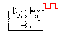 This is the square wave oscillator which used a CMOS-type logic inverters. I use the word "logic inverter" to avoid confusion with the DC/AC inverter. The output of the oscillator is connected with the drive circuit through the logic inverters. The antiphase signal of the alternating current is created using the logic inverter, too. Connect the input of the logic inverters not to be using with the grounding to avoid bad influence. As for the operation of the oscillator which used logic inverters, refer to "Square wave oscillator (2)". I chose resistance and capacitor for the oscillator in the following value. I calculated that it was possible to set to 50 Hz or 60 Hz with the variable resistor. Because there is an error of the part in the actual circuit, it is a reference value.
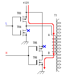
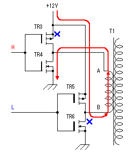
In the measurement result in the actual circuit, the minimum frequency was 43.6 Hz and the maximum frequency was to 76.6 Hz be. 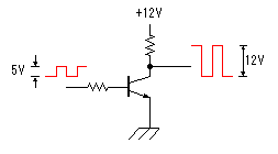 Because the output of the oscillator is the TTL of 0V to 5V, it is converted into the amplitude of vibration of 0V to 12V to drive an FET with this circuit. It is not a special circuit. This is the switching circuit which is the main circuit of the DC/AC inverter this time. I used C-MOS FET circuit by power MOS FET. Two sets of C-MOS FET circuits are used and are controlled by the antiphase.
When the input level is opposite, TR3 and TR6 become OFF condition and TR4 and TR5 become ON condition. Therefore, the electric current which flows through the transformer becomes contrary to the case of the above. Either above-mentioned condition is continued when the oscillator stops. Therefore, the big electric current flows on the secondary side of the transformer. The fuse must be put to protect. Refer to "The operation principle of C-MOS FET" about MOS FET and the C-MOS circuit. 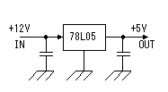 This is the circuit which is used 3 terminal regulator for +5V. It is OK with the 100mA type because it is only to drive IC1. |
