I did the performance measurement of the switching regulator which used LM2575-5.0.
The way of measuring is the way of increasing the output power, making the load resistance value small gradually. The measurement item is the change of the output voltage and the input electric current.
The characteristic when the load is rapidly changed is the important characteristic of the regulator. However, because I don't have the measurement receptacle, I am not measuring.
I calculate the output current, the input power, the output power and the efficiency by the formula below each.
| Output current(A) | = | Output voltage(V) / Load resistance value(ohm) |
| Input power(W) | = |
Input voltage(V) x Input current(A)
[Input voltage = 12V] |
| Output power(W) | = | Output voltage(V) x Output current(A) |
| Efficiency(%) | = | (Output power(W) / Input power(W)) x 100 |

 The change of the voltage and the current by the load change The change of the voltage and the current by the load change
When decreasing the load gradually, the output is maximized at about 2 ohm. At the load resistance value below it, the output voltage declines and the output power falls too. I think this change according to the limitation circuit of the output current to prevent from the damaging of the regulator by the over-current. At the data sheet, the limitation value is 2.2 A.
The guarantee value of the output current of LM2575-5.0 is 1 A. Because it is, when pouring the 2-A output current into the continuation, the normal operation of the regulator isn't guaranteed.
Be careful. |
The electric power change by the load change
The efficiency of LM2575-5.0 is about 80%. It is the very good value. Because the input electric power in case of 1 A of the output currents(5 W output) is 6 W, the loss of the regulator is 1 W.
In the measurement, about 11 W(2.2 A of output currents) are measured as the maximum output. Because the regulator loss in this case is about 1.5 W, the efficiency is about 88%. It is the very high efficiency.
This time, I attached the heatsink to the regulator but if being this loss, the heatsink is unnecessary.
In the result of the thermometry, the temperature rise is the small value. |
The ripple voltage
In case of the switching regulator, the ripple voltage occurs to the output in the relation of the operation.
The output wave form
in the no-load condition |
The output wave form
in the 5-W output |
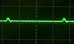
With the photograph above, the left side shows the ripple voltage which appears in the output in the no-load condition. Because the ripple voltage is about 10 mVp-p, it becomes about 0.2% of the ripples at the 5-V output voltage.
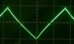
The photograph in the right shows the ripple voltage when the load current is 1 A (5 W output). Because the ripple voltage is about 100 mVp-p, it becomes about 2% of the ripples at the 5-V output voltage. However, by putting the secondary filter which combined the several-µH coil and the hundreds-of-µF capacitor, the ripple can be decreased. |
|
 |
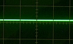
The secondary filter output wave form
in the 5-W output |
The photograph above is the one to have observed the output voltage of the secondary filter which connected with the output of the regulator.
The ripple voltage is hardly observed. It has less than 5-mV voltage(It is 0.1% at 5 V). |
I observed the photographs above in the same range.
|