Parts explanation
of +/-12V -> +/-5V Power unit
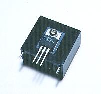
 This is the regulator that changes the input voltage of 12V to the 5V output voltage. It is possible for this regulator to change the output voltage in the range from 1.3 V to 37 V but this time, I am using it on the 5 V fixation. To output the 37 V voltage, 40 V are necessary as the input voltage.  This regulator is for the negative voltage. The polarity with the voltage is opposite only and the functionality ability is equal to LM317 approximately. Be careful because position of the input and the output pin are different from LM317. 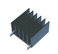 It installs in LM317 and LM337. It becomes hot when the 1 A output current flows through the regulator. In the case, the regulator breaks without the heatsink. It installs in LM317 and LM337. It becomes hot when the 1 A output current flows through the regulator. In the case, the regulator breaks without the heatsink.Formally, you decide the size of the heatsink with the calculation of the calorific value of the regulator. Because the actual calculation was troublesome, I used the a little biggish one. (It is difficult to judge the case which that is small is big, too) The heatsink is made with the aluminum alloy. The thermal conductivity is high and is the light one. As for the surface area of the heatsink, the radiation quantity increases more in the wider one. Therefore, the heatsink is doing the structure which has the fins. The size of the heatsink which I used this time is hereinafter. The 30-mm height, the 31-mm width of the surface which installs the regulator and the 20-mm depth to the direction of fin. The regulator is installed on the heatsink with the one screw. It depends on the kind of the heatsink but there is one where the heatsink itself has the pin for the fixation, too. The one which was used this time is doing the structure which inserts the two pins in the printed board.  It is possible to fix by bending a little after inserting the pin in the printed board. It is possible to fix by soldering to the printed board, too. Because I used the universal printed board, I inserted the 2-mm brass metal fittings to the pin and I fixed it by the soldering. It is possible to fix by bending a little after inserting the pin in the printed board. It is possible to fix by soldering to the printed board, too. Because I used the universal printed board, I inserted the 2-mm brass metal fittings to the pin and I fixed it by the soldering.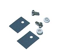 The back plate (the part which puts the heatsink) of the regulator is connected with the one of the pins. In case of LM317, it is connected with the output voltage pin. Also, in case of LM337, it is connected with the input voltage pin. You may put the regulator to the heatsink to direct if the heatsink doesn't touch the electric circuit. However, there is danger which short-circuits when touching the heatsink with the metal of the screwdriver and so on when the input or the output voltage is being applied to the heatsink. The back plate (the part which puts the heatsink) of the regulator is connected with the one of the pins. In case of LM317, it is connected with the output voltage pin. Also, in case of LM337, it is connected with the input voltage pin. You may put the regulator to the heatsink to direct if the heatsink doesn't touch the electric circuit. However, there is danger which short-circuits when touching the heatsink with the metal of the screwdriver and so on when the input or the output voltage is being applied to the heatsink.Therefore, when putting the heatsink to the regulator, I place the insulating material among them. I use the thin film, the silicon rubber, for this insulating material. It was using the mica before as the insulating material but the mica was the fact that it is easy to burn when taking fire and got to use the silicon rubber recently. It uses the 3mm screw to install the regulator at the heatsink. However, the about 4mm hole is opened at the regulator. This is because the screw makes not touch to the regulator, putting the circular insulation part to the hole of the regulator. You had better buy beforehand with the silicon rubber.
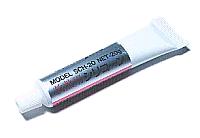 The silicon rubber is put between the regulator and the heatsink but the silicon grease is put in the thermal conductivity to improve. The silicon grease is the compounding of the white grease. The metallic oxide is mixed in it to improve the thermal conductivity. The silicon grease is painted the both sides of the silicon rubber and improves the heat conduction between the regulator and the heatsink. You don't need to paint a lot of it. There is not an effect in the part which was stuck out of the rubber. 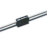 This is the diode to prevent regulator's breaking in the factor outside. I used the 1 A one. It is not necessary to use the diode with high reverse voltage. This time, I used the cheap one of 100 V. Be careful in the direction of the installation. 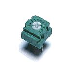 This is the variable resistor to adjust the output voltage. Because the electric current which flows through this resistor is about 10 mA, it is enough at usual small variable resistor. In case of 500 ohm, it is 0.01A x 0.01A x 500ohm = 0.05W. 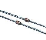 The 120-ohm resistor is used to pass the minimum output current of the regulator. Also, 1K-ohm is used for the electric current control by the LED. It is enough in the 1/8 W one. 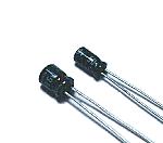 At the regulator itself, the ripple(Alternating voltage in the DC voltage) is suppressed, but moreover it puts these capacitors and makes the ripple little. The WV(Working Voltage) must be decided in the voltage to use. As for the small one in case of 1 µF, 50WV is general. The voltage of (VOUT-1.25V) is applied to the 10 µF capacitor. Because it is, in case of the 37 V output voltage, about 50 WV is necessary. This time, because the output voltage is 5 V, it is enough in 10WV. Actually, I used the one of 16WV. 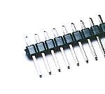 This is the terminal to connect the cable of the input and the output. It is not necessary to use the one of this shape. Also, if connecting the wire with direct to the printed board, it is not necessary to use this terminal. 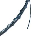 I used the tin plating wire with the 0.6-mm diameter for the circuit which the big electric current flows through. With the wire with the 0.32-mm diameter, in case of the 1-A electric current, there is not a problem. Way, in case of the wire with the 0.5-mm diameter, it is said that the electric current which is 15 A when the ambient temperature is 30°C can pour. It may depend on the kind of the wire little. 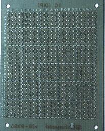 I was irresolute about whether or not to use the printed board or the universal printed board when I made the circuit this time. I decided to use the universal printed board from the easiness of the creation. I used the one of 25 halls x 30 halls. The universal printed board 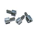 I use this to install the printed board to the case. There is not necessity of the metal. 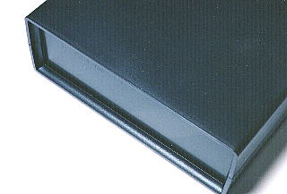 I used the cheap plastic case. You consider the height of the heatsink and the size must be decided. It makes a hole in the bottom and the top for the heat of the regulator to be produced outside. The size of the case which I used this time has the 150-mm width, the 54-mm height, the 170-mm depth. I enter the letter on the front panel to understand the name of the terminal. Also, I did to understand the input terminal, the output terminal immediately. At the maker product, it is beautifully printed with the silk print. However, when homemade, the silk print isn't simply made. There was a way of using the lettering seal, too, but this time, I made in the way of putting the color sheet with the printer among the transparent acrylic sheet.  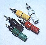 I am using this terminal as the terminal of the input and the output. It doesn't make a mistake in the terminal when considering the color to use. This terminal can use the banana plug that the attaching or removing is easy. Also, the wire can be stopped by putting in it, too. 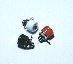 This is the jack which inserts the banana plug. The wire can not be put in like the Johnson terminal. I used this terminal as the input terminal. 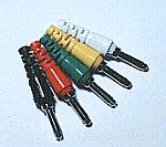 By installing this plug in the wire of the input/output, the wire can be easily attached or removed. 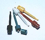 I put this plug to the tip of the output wire. The J-type reed goes out of the tip when pushing the top of the plug and can hitch to the terminal or the wire. Because the top turns back with the spring, the reed of the tip disappears and can connect tightly when relaxing the power to push. I used the big type to use for the power supply cable. 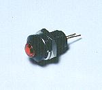 It is making the LED lamp light up at the input voltage of +12 V. It is putting the resistor for the electric current of the LED to become about 10 mA. It becomes about 10 mA when using the resistance of 1K ohm. It is possible to make light up at output's 5 V, too, but because it applies the extra electric current to the regulator, I am using the input voltage. I think that it is good that you put the LED to both with the positive voltage and the negative voltage, too. |