14 Bit Binary Counter And Oscillator (4060B) 14 Bit Binary Counter And Oscillator (4060B)
This IC has the inverter for the oscillator and the 14-bit binary counter which divides the oscillator output.
Make the circuit this time oscillate 4.096 MHz and it is using the output of the 12th bit (1/4096=1KHz) of the binary counter.
(Top View) |
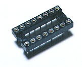
The circuit which handles the comparatively high frequency had better use the one with the circular shape of pin as the IC socket. |
 Characteristic Characteristic
 | The oscillation circuit and the binary counter which was equipped with the flip-flop of the 14 stages |
| By doing the RC or the crystal oscillator in the external, the oscillator can be composed inside. |
| It counts the clock with the falling edge. |
| It has the tap output by the 4, 5, 6, 7, 8, 9, 12, 13, 14 stages. |
| The reset terminal resets in the H condition. |
Phase Locked Loop(4046B)
This IC is composed from the phase comparator which detects the difference between the reference frequency and the comparison frequency and the VCO which generates the digital pulse.
There are two kinds of phase comparators. As for the 1st, it outputs the phase difference of the input signal (the reference frequency and the comparison frequency) simply as the pulse duration (The output 1). As for the 2nd, it outputs the phase difference of the input signal at the pulse duration and in the polarity (The output 2).
The circuit this time is using the output 2.
The VCO can make oscillate in about 1 MHz. The minimum frequency and the maximum frequency are decided at the value of R4, R5 and C4. Each relational expression is as follows.
| The minimum frequency(fmin) | = | 1/(R5(C4+32pF)) |
| The maximum frequency(fmax) | = | (1/(R4(C4+32pF))) + fmin |
Programmable BCD Counter (4522B)
At one of 4522, the 0-9 dividing can be done by the BCD specification of the 1 digit.
The basic operation is as follows.
| It reads the condition (the condition of the BCD switch) of the BCD specification terminal when PE(Preset Enable) becomes H from the L. |
| Every time CLOCK became H from the L, it subtracts 1 from the value which was read . (Decrement) |
| The condition of the "0" output becomes H from the L when the subtracted value becomes 0. |
4522 has the CAS(Cascade feedback) terminal. When this terminal is in the L condition, the "0" output doesn't become H.
Because it is, in the dividing of more than one figure, when connecting the "0" output of the higher rank figure with the CAS terminal of the lower rank, when the subtraction that the higher rank is the number of the specification doesn't complete, "0" of the lower rank figure doesn't become the H condition.
By connecting the Q4 output of the lower rank with the CLOCK terminal of the higher rank, CLOCK of 1/10 is inputted to the higher rank.
 |
| (Top View) |
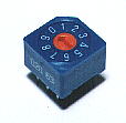
BCD switch
I used the rotary-type BCD switch.
This switch has the graduation from 0 to 9 and the switch closes as follows with each position.
| Terminal | Position |
| 0 | 1 | 2 | 3 | 4 | 5 | 6 | 7 | 8 | 9 |
| 1 |
|  |
| |
| |
| |
| |
| 2 |
|
| | |
|
| | |
|
|
| 4 |
|
|
|
| | | | |
|
|
| 8 |
|
|
|
|
|
|
|
| | |
The mark shows the terminal which is connected with COMMON.
 |

(Bottom View) |
|