[Menu]>[Electronic circuit beans collection]


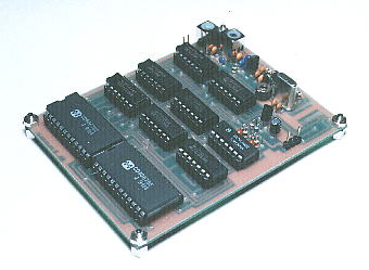
PLL synthesizing oscillator (1)


Block diagram of the top is a clickable image map.
You can jump to each page of the explanation when you click each block.


The PLL synthesizer oscillation circuit to introduce here is using the PLL frequency synthesizer (MB87014A). It is possible to make oscillate the stable high frequency signal.
The PLL is the abbreviation of Phase Locked Loop. In the operation of the PLL, it compares the frequency of the reference frequency oscillator and the frequency of the voltage controlled oscillator by the phase. When there is a difference of the phase, it works as if to control the VCO and to lose the difference. It controls repeatedly(loop) like the oscillation frequency phase comparison voltage control oscillation frequency.
It uses the crystal oscillator with the high stability for the reference frequency oscillator. Because it isn't possible to make oscillate the high frequency only with the crystal oscillator, the stable high frequency signal can be made by comparing the frequency with the divider changing into the comparatively low frequency.

The frequency which was stable as the characteristic of the PLL synthesizer can be gotten but there is a point which can change the output frequency in changing the dividing percentage of the divider as another characteristic.
The circuit to introduce this time makes the dividing percentage the fixation.

It made the oscillator to introduce this time in the purpose to use as the oscillator of the transceivers for 144 MHz to use by the amateur radio. That the output frequency is 119.3 MHz is due to the following reason.
This PLL oscillator is used as the sub oscillator of the main PLL oscillator.


Principle of the PLL oscillator
    The constitution of the PLL oscillator is as follows.


Reference frequency oscillatorThe high stability oscillator like a crystal oscillator etc. are used.
Voltage controlled oscillator ( VCO )This is the oscillator that frequency changes by voltage control.
Phase comparator The comparative difference between reference oscillation frequency and output frequency is detected.
In the case that there is a difference the control voltage is output.
In the case that the output frequency is high the voltage that lowers frequency to VCO is output.
Programmable counter Dividing output frequency comparative frequency is made.
Output frequency can be changed by changing the counting value.


Circuit drawing

Pattern drawing

Parts mounting drawing

Adjustment

Circuit explanation