Circuit explanation
of Digital dial
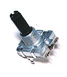 This time, the encoder which I used is EC16B which is made by the ALPS electricity company in Japan. The encoder has three terminals, and one is allocated for common terminal (COM) and the other two are a terminal for the output. The output terminal becomes the condition whether or not which connects with the common terminal or whether or not it is not. Two terminals for the output differ in the timing which touches a common terminal when the axis of the encoder is turned. The output relation in case of EC16B becomes like the following figure. 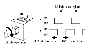 The standard data of EC16B
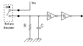 The circuit this time is using capacitor(C) to prevent from the chattering. The chattering is the phenomenon which repeats slight time ON, OFF when the switch connects. This is the phenomenon which comes out when using a mechanical switch. The electronic circuits has detected ON, OFF of this short time and sometimes malfunctions. When not using the chattering prevention circuit, more than one count sometimes rises in spite of being only one count. It is using Schmidt trigger-type inverter (7414) to arrange a waveform. In the Schmidt trigger-type inverter, the circuit which is called " the Darlington connection" is used. This is the circuit which connects a collector at the pre-stage with the base at the following stage directly. The output turning-over of the inverter becomes high-speed with this way. 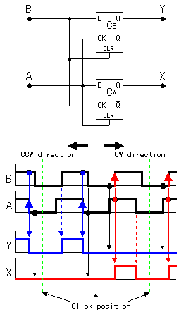 It is the circuit which judges whether it is a CW or a CCW compared with two pieces of output from the encoder. It used D-type flip-flop (7474) for the judgement. The D-type flip-flop makes the operation to output the output terminal (Q) in the condition of the D input terminal when the clock(CK) changes into the H condition from the L condition. Operation by the clockwise(CW) is explained. When the A point changes into H from the L, the clock (CK) of ICB changes into H from the L and ICB becomes the condition to take in D input. However, at this point, the B point is in the L condition and the clear terminal of ICB is in the L condition. Therefore, the output (the Y point) of ICB keeps an L condition. Because the clear terminal is always an L when the clock (the A point) of ICB becomes H from the L in the CW, the condition of ICB doesn't change. Next, the B point changes into H from the L. This changes the clock (CK) of the ICA from the L to H and the ICA becomes the condition to take in D input. The output (the X point) of the ICA changes into H from the L because the A point becomes H condition already at this point and a cleared condition is already canceled. An ICA is initialized by the clear terminal of the ICA and the output (the X point) of the ICA changes into the L from H when the turn moves ahead and the A point changes into the L from H. When moving an encoder to the right in 1 click like above explanation, one pulse is output on the X point. In case of CW, the pulse doesn't develop on the side of the Y point. The pulse occurs to the X point every time it clicks to the right. It works like the CW in case of CCW, too. In case of the CCW, because the B point changes into H from the L earlier than the A point, the pulse doesn't develop on the side of the X point. The pulse occurs to the Y point every time it clicks to the left. By above operation, it does the judgement of the CW, the CCW and the pulse occurs to each output terminal every time it clicks. The BCD is the abbreviation of Binary Coded Decimal. It is the counter which returns to 0 in the next pulse with the count rising from 0 to 9. It used 74192 for the counter. There are input for addition (UP) and input for subtraction (DOWN) in this counter. As for the output from the up down judgment circuit, it inputs a pulse in case of CW to UP and it inputs a pulse in case of CCW to DOWN. It makes a clear terminal H condition with the capacitor and the resistor to make display zero in case of the turning on. 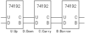 At the circuit to introduce this time, it is a 1-digit counter, but 74192 has the terminal of carry and the terminal of borrow, too, and it is possible to more than one digit count. At the circuit to introduce this time, it is a 1-digit counter, but 74192 has the terminal of carry and the terminal of borrow, too, and it is possible to more than one digit count.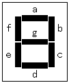 It is the driver to drive an LED for the digit present in 7 segments. It drives each device in 7 segments by the input of BDC. The relation between BDC and each device in 7 segments is as follows.
It uses an LED for the digit display which used 7 segments (seven devices). Because there is various size, use liked one. But, when using with the circuit this time, use an anode common type. Two kinds are in the LED in 7 segments. They are an anode common and a cathode common. 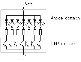  The resistors for the electric current control of the LED must be put every each segment. The number of the lighting LED devices depends on the figure to display. When putting a resistor in the common part, the light of the LED has changed every figure to display. |
||||||||||||||||||||||||||||||||||||||||||||||||||||||||||||||||||||||||||||||||||||||||||||||||||||||||||||||||||||||||||||||||||||||||||||||||||||||||||||||||||
