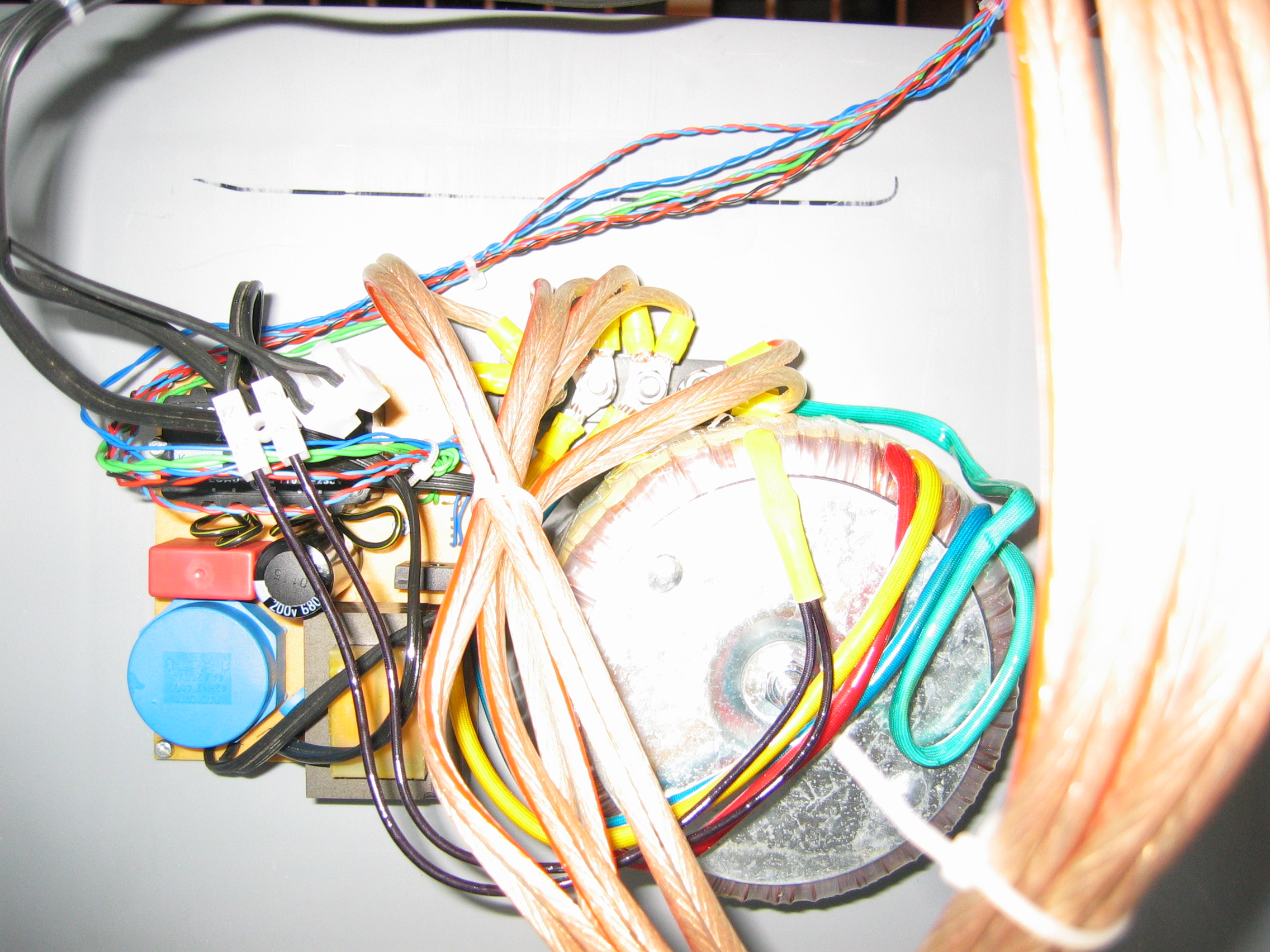
This page showes you the a close up of the electronics used in the station

As you can see, there is no rocket sience involved when it comes to the electronics. The station mainly consist of a PCB which holds a small transformer that feeds two voltage regulators and simple lamp dimmer. The latter's output goes to the main transformer you can see on the right hand side. The two secondary coils of the transformer then go to four rectifiers which can get warm. That's why I added a CPU coller and fan to keep them cool. The two menioned voltage regulators are here to feed the cooler fan and of couse also the swing mechanics motor. This motor is having a gear with a 1:360 ratio.
The power parts mentioned and the big capacitor were not well suited to be also placed on a PCB and hence they are mounted on their own.
If someone is interested in the PCB layout or needs more information about this part drop me an e-mail. See the main page for the address.
| file: /Techref/pcb/plating/tps-electronics.htm, 1KB, , updated: 2009/10/23 12:32, local time: 2025/10/19 05:55,
216.73.216.53,10-2-207-162:LOG IN
|
| ©2025 These pages are served without commercial sponsorship. (No popup ads, etc...).Bandwidth abuse increases hosting cost forcing sponsorship or shutdown. This server aggressively defends against automated copying for any reason including offline viewing, duplication, etc... Please respect this requirement and DO NOT RIP THIS SITE. Questions? <A HREF="http://techref.massmind.org/Techref/pcb/plating/tps-electronics.htm"> Homebrew Through Hole PCB Plating Station - Electronics</A> |
| Did you find what you needed? |
Welcome to massmind.org! |
|
The Backwoods Guide to Computer Lingo |
.