w. v. ooijen / f. hanneman [wf@xs4all.nl] says:
Actually you can drive 9 [seven segment] displays (of seven segments + point) with 9 pins. [or 8 displays excluding the point with one port of 8 pins]. But this takes a bit more code. The trick is to use both the high, low and input states. Each display has its anode on one of the lines, and all of its cathodes's on the other 8 lines. Now to light one segment you make the pin connected to that displays anode positive, that segments cathode negative [or ground], and (this is the trick) all other lines inputs. Of course you multiplex one display at a time, not one segment.[Ed: for anyone (like me) who didn't get that on the first reading, maybe this will help: each pin of the uP port is connected to 1 displays anode and to one of the the other 8 or 9 displays segments. e.g. pin1 = disp1anode & disp2a & disp3b & disp4c & disp5d & disp6e & disp7f & disp8g, pin2 = disp1a & disp2anode & disp3b & disp4c & disp5d & disp6e & disp7f & disp8g, etc...]

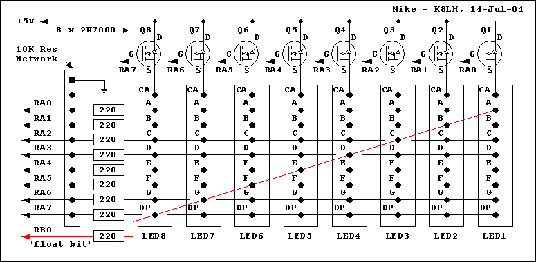
Mike McLaren's [k8lh@arrl.net] untested 9-pin 8-digit design (19-Jul-04):
The INIT section of the main program will need to initialize BITPOS to b'00000001', set BUFPTR to point at the the eight byte digit buffer, and setup RB0 as an output before turning on the interrupt source (Timer2 in my case)... The main program then simply stuffs the eight byte digit buffer with each digits segment data (bits 6..0 = segments G..A, respectively) and decimal point (bit 7)... Suppress a leading zero by setting that digits buffer to b'00000000' and perform a "lamp test" by setting all eight digit buffers to b'11111111'... The 9-pin design easily supports a 9th digit but the code gets a little bigger when we start manipulating TRISB and PORTB...
 ; 8-digit 9-pin LED display sample ISR code...
 ;  (14-bit core instructions)
 ;
 ; Vars - BITPOS (float bit & digit position)
 ;        BUFPTR (buffer pointer)
 ;        DIGIT1 (start of 8 byte display data buffer)
 ;               (bit 7=dp, bits 6..0=segments G..A)
 ;
 ISR_LED  bsf   STATUS,RP0   ;Bank 1 (RP1 is clr)     |B1
          movlw b'11111111'  ;                        |B1
          movwf TRISA        ;turn off display        |B1
          bcf   STATUS,RP0   ;Bank 0 (RP1 is clr)     |B0
          movf  BITPOS,W     ;example: b'00000001'    |B0
          movwf PORTA        ;new output pattern      |B0
 ;
          bsf   PORTB,0      ;turn 'float bit' off    |B0
          movf  BUFPTR,W     ;ptr to current digit    |B0
          movwf FSR          ;setup indirect address  |B0
          movf  INDF,W       ;get digit segment data  |B0
          andwf BITPOS,W     ;AND float/column bit    |B0
          btfss STATUS,Z     ;need the float bit?     |B0
          bcf   PORTB,0      ;yes, 'float' bit on     |B0
          iorwf BITPOS,W     ;pickup the BITPOS bit   |B0
          iorwf INDF,W       ;get digit segment bits  |B0
          xorlw b'11111111'  ;invert all bits         |B0
          bsf   STATUS,RP0   ;Bank 1 (RP1 is clr)     |B1
          movwf TRISA        ;display new digit       |B1
          bcf   STATUS,RP0   ;Bank 0 (RP1 is clr)     |B0
 ;
          incf  BUFPTR,f     ;increment buffer ptr    |B0
          bcf   STATUS,C     ;clear carry bit         |B0
          rlf   BITPOS,f     ;shift our digit bit     |B0
          btfss STATUS,C     ;all 8 digits scanned?   |B0
          goto  ISR_NXT      ;no, branch              |B0
 ;
          rlf   BITPOS,f     ;reset to b'00000001'    |B0
          movlw DIGIT1       ;get buffer address      |B0
          movwf BUFPTR       ;reset the pointer       |B0
 ;
 ISR_NXT
Questions:
It seems that this design idea requires that the seven segment displays do not have common cathods or annodes. I do not seem to be able to find 7 segment modules like this.
James Newton replies: Not so. There are multiple displays and the common cathode from each one is seperated, but the segments in one display are on a common cathode.+
See:
Comments:
Good idea instead, but the note is somewhat complicated and has a small error. Simply connect D0 to disp0an + disp[1:7]a, D1 to disp0b + disp1an + disp[2:7]b and so on (the editor connected both pin1 and pin2 to disp3a...)+Drawback is that you need 7 resistors per display (8 when you use the dot as well).
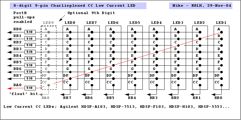
Mike McLaren's [k8lh@arrl.net] 9-pin 8-digit display design (29-Nov-04):

The Agilent low current displays eliminate the need for digit driver transistors... The INIT section of your main program will need to initialize BITPOS to b'00000001', set BUFPTR to point at the the beginning of your eight byte digit buffer, turn on Port B weak pull-ups, and setup RA0 as a digital output before turning on the interrupt source (I use TMR2)... The main program then simply stuffs the eight byte digit buffer with each digits segment data (bits 6..0 = segments G..A, respectively) and decimal point (bit 7)... Suppress a leading zero by setting that digits buffer to b'00000000' and perform a "lamp test" by setting all eight digit buffers to b'11111111'... The 9-pin design will support a 9th digit but the code would become a little more complex...
 ;
 ; 8-Digit 9-Pin Charlieplexed CC LED ISR Sample Code
 ;   (14-bit core instructions)
 ;
 ; Vars - BITPOS (float bit & digit position)
 ;        BUFPTR (buffer pointer)
 ;        DIGIT1 (start of 8 byte display data buffer)
 ;               (bit 7=dp, bit 6=G...bit 0=A)
 ;
 ISR_LED  bsf   STATUS,RP0   ;Bank 1 (RP1 is clr)     |B1
          movlw b'11111111'  ;                        |B1
          movwf TRISB        ;turn off display        |B1
          bcf   STATUS,RP0   ;Bank 0 (RP1 is clr)     |B0
          xorwf BITPOS,W     ;inv float/column bits   |B0
          movwf PORTB        ;new output pattern      |B0
 ;
          bcf   PORTA,0      ;turn 'float bit' off    |B0
          movf  BUFPTR,W     ;ptr to current digit    |B0
          movwf FSR          ;setup indirect address  |B0
          movf  INDF,W       ;get digit segment data  |B0
          andwf BITPOS,W     ;and float/column bit    |B0
          btfss STATUS,Z     ;need the float bit?     |B0
          bsf   PORTA,0      ;yes, 'float' bit on     |B0
          iorwf BITPOS,W     ;pickup the BITPOS bit   |B0
          iorwf INDF,W       ;get digit segment bits  |B0
          xorlw b'11111111'  ;invert all bits         |B0
          bsf   STATUS,RP0   ;Bank 1 (RP1 is clr)     |B1
          movwf TRISB        ;display new digit       |B1
          bcf   STATUS,RP0   ;Bank 0 (RP1 is clr)     |B0
 ;
          incf  BUFPTR,f     ;increment buffer ptr    |B0
          bcf   STATUS,C     ;clear carry bit         |B0
          rlf   BITPOS,f     ;shift our digit bit     |B0
          btfss STATUS,C     ;all 8 digits scanned?   |B0
          goto  ISR_NXT      ;no, branch              |B0
 ;
          rlf   BITPOS,f     ;reset to b'00000001'    |B0
          movlw DIGIT1       ;get buffer address      |B0
          movwf BUFPTR       ;reset the pointer       |B0
 ;
 ISR_NXT


 ;
 ; 8-Digit 9-Pin Charlieplexed CC LED ISR Sample Code
 ;   (16-bit core instructions)
 ;
 ; Vars - BITPOS (float bit & digit position)
 ;        BUFPTR (buffer pointer)
 ;        DIGIT1 (start of 8 byte display data buffer)
 ;               (bit 7=dp, bit 6=G...bit 0=A)
 ;
 ISR_LED  movlw b'11111111'  ;
          movwf TRISB        ;turn off display
          comf  BITPOS,W     ;invert for common cathode
          movwf PORTB        ;new output pattern
                             ;11111110, 11111101, etc.
          bcf   PORTA,0      ;turn 'float bit' off
          lfsr  2,BUFPTR     ;ptr to current digit
          movf  INDF2,W      ;get digit segment data
          andwf BITPOS,W     ;AND float/column bit
          btfss STATUS,Z     ;need the float bit?
          bsf   PORTA,0      ;yes, 'float' bit on
          iorwf BITPOS,W     ;pickup the BITPOS bit
          iorwf INDF2,W      ;get digit segment bits
          xorlw b'11111111'  ;invert all bits
          movwf TRISB        ;display new digit
 ;
          incf  BUFPTR,f     ;increment buffer ptr
          rlncf BITPOS,f     ;setup for next digit
          decf  BITPOS,W     ;column 00000001?
          bnz   ISR_NXT      ;no, branch
                             ;else, reset pointer
          movlw DIGIT1       ;get buffer address
          movwf BUFPTR       ;reset the pointer
 ;
 ISR_NXT
Archive:
| file: /Techref/io/led/8x7s8pin.htm, 23KB, , updated: 2009/12/3 09:57, local time: 2025/10/10 04:01,
owner: kan-MMM-UA4,
216.73.216.137,10-3-124-149:LOG IN
|
| ©2025 These pages are served without commercial sponsorship. (No popup ads, etc...).Bandwidth abuse increases hosting cost forcing sponsorship or shutdown. This server aggressively defends against automated copying for any reason including offline viewing, duplication, etc... Please respect this requirement and DO NOT RIP THIS SITE. Questions? <A HREF="http://techref.massmind.org/Techref/io/led/8x7s8pin.htm"> Driving 8 or 9 7 segment displays with 8 or 9 io pins (and no extra circuitry)</A> |
| Did you find what you needed? |
Welcome to massmind.org! |
|
The Backwoods Guide to Computer Lingo |
.