(first draft; 11th Nov 2009)

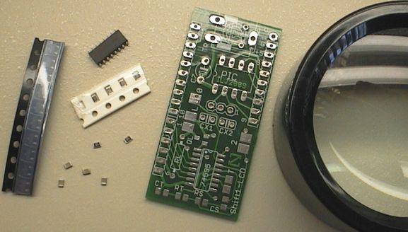
Step 1: The surface-mount components.
It helps to have a magnifying glass. Also, a headband type magnifier or magnifying glasses are very handy.
These (surface mount) SMD components are of the larger size 0805 and SOIC so they are not very difficult to solder, you can do it with a fine point soldering iron. There are only 6 SMD parts so it only takes 10 minutes.
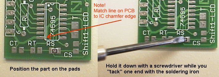
Try not to let the part move and become crooked like in the photo above.
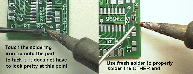
The part is tacked on one end to hold it in place. The tack will never look pretty, as you can see above. But it will be re-soldered later.
Keep the soldering iron tip clean by constantly applying fresh solder and wiping off the old solder. The tip on the left is fairly clean, the one on the right is dirty, due to the delays and problems in taking close-up photos.
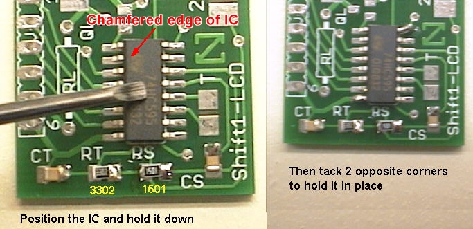
Solder the 4 small parts (see below). The two capacitors CS and CT are both 2.2nF (2n2) and it doesn't matter what orientation you solder them in. The two resistors are marked 3302 (33k RT) and 1501 (1k5 RS). You must put the two resistors in the right places! Also, it is nice to orient them so you can read their markings. Allow plenty of time (5 seconds) between soldering each side of the parts!
Above you can see the 4 small parts are tacked at one end and waiting to be soldered. That will be done after the IC has been tacked.
The IC MUST be oriented correctly. See the photo, and the description here:
Note! The 74HC595 IC does not have the typical dot-indent orientation instead one edge has a slight chamfer. Match the IC CHAMFER edge to the IC white double line marked on the PCB.
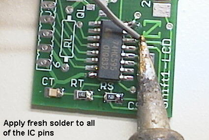
After tacking the IC in position, start soldering its pins. Solder 2 or 3 pins at a time, this is much easier than trying to solder single pins. Don't worry when you get excess solder and pins join or "bridge". The main goal is to get fresh clean solder applied to all the pins.
Make sure the soldering iron tip is MUCH cleaner than in the staged photo above!
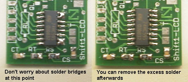
Above you can see some solder bridges, this is normal. Excess solder is removed by touching the soldering iron tip onto the bridge and the solder transfers onto the tip. Remove excess solder first from the tip by wiping it, if the tip already has significant solder on it it won't draw the solder from the bridge.
Some people use solder wick or fine braided wire to suck the excess solder from the bridge but that is not really necessary. Keep applying fresh solder to the tip to clean it, then remove excess solder from the tip, then without waiting touch the tip to the solder bridges.
You can also see above that the 4 small parts have been soldered now too. These are soldered by applying fresh solder to both sides. Allow enough time between soldering each side so the part does not become too hot, you don't want both solder joints of the part to melt at once or it will move, or even worse it will stick to the soldering iron tip!
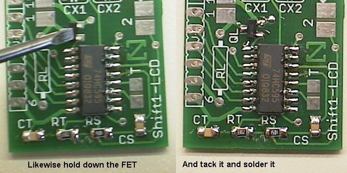
Now solder the FET (QL). This can only go one way around. Note! The FET is only needed if you are using the auto backlight switching feature. If the LCD backlight will always be ON or OFF, the FET is not needed.
Above you can see the messy flux, like clear brown lumps over the solder joints you have made. When the flux has cooled you can gently scratch it off using a small flat screwdriver. It chips off very easily.
Then brush the chips away with a DRY nylon toothbrush. If you want to be extra neat then after dry brushing you can brush with a toothbrush wetted with some metho or isopropyl alcohol. Then dab the PCB dry on a tissue.
Most fluxes are safe to leave on the PCB, removing the flux is done mainly for cosmetic reasons.
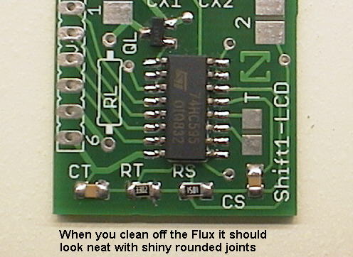
Inspect the solder joints carefully with a magnifier glass and bright light. It is much easier to inspect the joints after flux removal. Good solder joints will be very round, and shiny, and properly "wetted" to the part and to the PCB pad. Joints that are lumpy or spiky may need to be resoldered with fresh solder applied.
Joints that are frosted or grey MUST be resoldered. Obviously you should make sure there are no solder bridges between the IC pins, use the magnifier and a very bright light to check this!
The soldering you can see in the photo above is not fantastic, you can see the caps are soldered better than the resistors. The soldering on the IC and FET looks ok. Everything here is good enough and will be 100% functional.
Don't be put off by the long explanations above. There are only 6 SMD parts to solder and it is a lot quicker and easier to do than it is to explain!
Step 2: The through-hole parts.
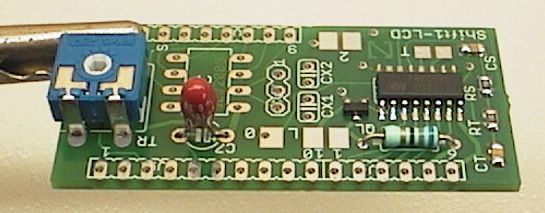
Insert and solder the blue 10k trimpot (TR).
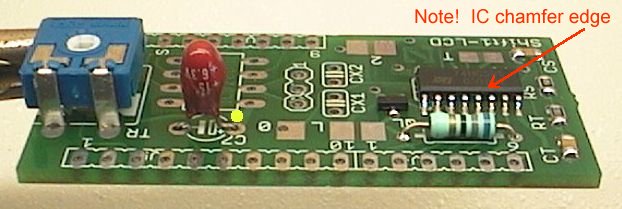
Then do the 15uF 6.3v tantalum cap (C7). Scrape its legs gently with pliers before soldering (if they look dull). It must be oriented correctly, see its + pin marked by the yellow dot in the photo above. You might need a magnifying glass to see the little + sign on the cap, the markings are quite small.
Next is the 68 ohm resistor (RL). This controls the brightness of the LCD display's LED backlight, if the display has a backlight.
You might want to do some testing here and choose a different value resistor. This depends on the make and type of your LCD and how bright you want the backlight to be. The 68 ohm resistor gives a low brightness backlight using very little power (about 25mA) but the display will still be readable in darkness. If you want a very bright backlight you can use a lower value resistor (like 10 ohms or 22 ohms) but you should check with your LCD datasheet as there are many different types. The FET is rated at 1.4 amps, and the very bright backlights can be rated as high as 500mA.
Of course if you are not using the LCD backlight you don't need this resistor at all (and you don't need the FET).
Step 3: Insert and solder the header pins.
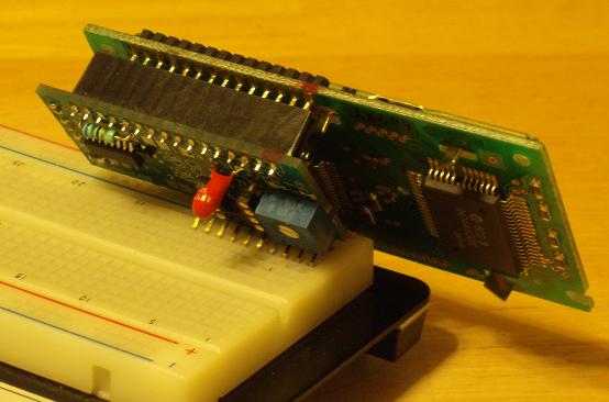
The straight header (16 pins) goes under the PCB, this allows the Shift1 PCB to be mounted directly behind the LCD.
(Option 1) The other side of the 16 pin header can be soldered direct onto the LCD. This gives a secure mounting, good for permanent installation.
(Option 2) The 16 pin socket (provided) can be soldered on to the LCD, this way the Shift1 can be "plugged" onto the back of the LCD. This is a less secure mounting but allows different LCDs to be plugged in.

The photo above shows the Shift1 in its basic form. This is complete and can operate an LCD and backlight using just one pin (signal) and 2 power pins (+5v and Ground).
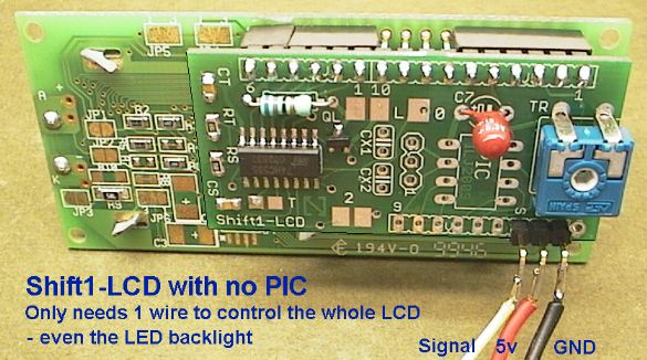
The right-angle header only needs 3 pins if the Shift1 does not have the on-board PIC. It only requires; S (signal), +5v and Gnd. These are marked on the PCB. However you can solder the whole 10 pin header if you choose, or snap 3 pins off the header strip and solder only 3 pins (see above). If you bend the pins on the right-angle header out to about 45 instead of 90 degrees, the Shift-1 and LCD panel will mount nicely on the edge of a standard whiteboard (thanks to Joe Watson).
Step 4: PIC option.
If you want to have an 8 pin PIC microcontroller on-board the Shift1 you can solder an 8 pin socket. Check the orientation, the notch on the socket goes at the top (see the yellow dot on the photo).
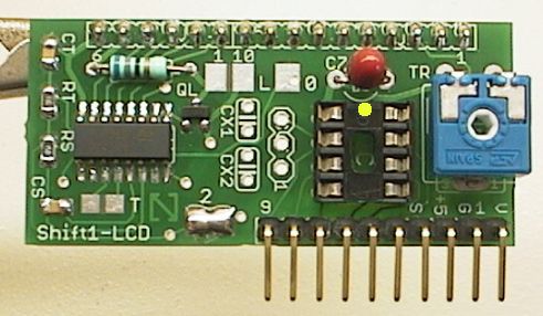
If using the on-board PIC you must join the solder jumper marked as '2'.
Since the PIC has an internal oscillator you don't need the xtal for many applications. The photo above shows a Shift1 with PIC socket installed. This can be a complete controller, like a temperature controller or solar battery charge controller, see the Shift1 projects page.
Step 5: PIC and xtal option.
The xtal (crystal) allows the on-board PIC to do precise timing like clock and timer applications. The Shift1 projects mainly use an 8MHz xtal and two 22pF capacitors.
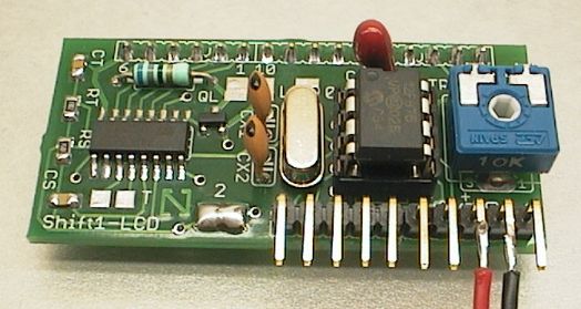
Insert the xtal but make sure it is 1mm or so above the PCB when soldered. This reduces strain on its legs ands stops it touching the square pad marked as '0'.
Pre-bend the legs of the two 22pF ceramic caps (CX1 and CX2). Solder them slightly above the PCB too to avoid leg strain.
Step 6: 5v regulator option.
A standard 7805 +5v regulator can be mounted directly on the Shift1. This allows the Shift1 to be operated from +12v (for instance) as the 7805 converts the +12v supply to +5v required by the Shift1 and the LCD.
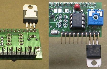
There is a blank pad marked 'V' which is used for this purpose. The 7805 is soldered directly onto the first 3 pads; Vin, Gnd, +5v. It is best to do this after soldering the header pins (see the photo above).
In most cases a heatsink on the 7805 is not required, unless you are running a high power LED backlight.
Step 7: Testing.
Check all the soldering! Go over the SMD soldering with a magnifier glass. Also check the other soldering on the bottom of the PCB.
Check the orientation of the 74HC595 shift register IC, and the PIC (if you use the PIC option). Also check orientation of the tantalum cap C7.
Check the placement of SMD resistors RS and RT.
The solder jumpers
Jumper 2. Join this when using the on-board PIC. This connects the PIC pin GP2 to the shift register IC.
Jumper L. Join this to turn the LCD backlight permanently ON. If this jumper is joined you no longer need the backlight control FET (QL).
Jumper T. Don't join this jumper! This is only to be used in special circumstances! If you join jumper T you must remove SMD cap CT. Then the shift clock and transfer clock of the shift register are joined. This means you can use the full 8bit capability of the shift register IC, but it also means the shift register outputs will change as data is shifted in, so this mode is NOT SUITABLE for LCD driving. This should be considered a special mode only for use in some special circumstances like LED multiplexing and also requires special driver firmware.
Pad 0. The pad marked as '0' connects to the shift register IC bit0. This is not used in normal use and can only be used in special circumstances like when using jumper T (see above). Don't connect anything to this pad.
Step 8: Troubleshooting.
Note! Always check and adjust the blue trimpot TR. This sets the LCD contrast, and if this is not adjusted correctly the LCD will not show any characters. This is the most common cause of the LCD not working!
For the LCD to display something you need to drive it with the on-board PIC or with a signal from an external PIC or other microcontroller.
http://www.romanblack.com/shift1/sh1_projects.htm The shift 1 project page has lots of project ideas that you can do just by adding a PIC and loading it with the supplied code: A clock, servo tester, charge controller, tachometer, temperature guage / thermostat, drying oven controller, dual ultra capacity counters, morse code trainer, and more!
Be aware that some of the Shift1 projects require a xtal (and two 22pF caps) but other projects just require the onboard PIC itself with no xtal.
A simple adapter can be made to provide in circuit programming for an onboard PIC. See the main Shift-1 page for this information.
(end)
The Shift 1 is designed to directly connect to a standard 1x15 LCD panel. If you want to use it with the LCD Panel 1, you can wire them together
Questions:
These are such cool devices! I have implemented several of the Shift1 projects. Now I am at the point where I would like to modify the source code and recompile it but when I attempt a build (even without making changes) with the MikroC compiler I get two consistent errors: Redefined: SH1_LCDbacklight in shift1_lcd.c, Redefined: SH1_trashdata in shift1_lcd.c I have not yet been able to discern where these terms are being redefined - the errors reference lines 20 and 23 at the beginning of the program.
Any ideas?
James Newton of MassMind replies: Not being a MikroC user, I'm not sure I can help, but typically, a redefinition means that the function was referenced before the actual definition which can happen if the files aren't set up in the project correctly. Roman or the MikroC forums would be a good place to ask for more help.+
+ nerdmedic~NOSPAM~ at gmail.com replies:
James - you pointed me in the right direction. When I created the project file in MikroC, being a noob I had included both of the source code files in the project (SH1_temp.c and SH1_LCD.c) - because SH1_LCD.c is referenced in the primary file by an include directive, it was being processed twice and hence the redefinitions. As you surmised, it was indeed a case of the files not being set up properly in the project... thanks!+
Comments:
One other note - I used the 7805 option to regulate the voltage and to cure some noise problems, I solder an SMD capacitor between each set of legs on the 7805 leads themselves. A pair of 1206-size capacitors works perfectly and I use 0.33 uF between input and ground and 1.0uF between output and ground. Then I solder the 7805 to the first three pins of the 10-pin connector and bring in my supply voltage, typically a 9v battery but sometimes 12v from an auto cigarette lighter plug. This works very well and has eliminated the noise-related issues I initially saw.
I am having a bunch of fun with these boards, using them for different applications that run on the 12F675 PIC. For versatility, I use the option of soldering a 7805T on the first three pins as shown above. To eliminate any problems with noise, I have been soldering two capacitors to the 7805T itself before soldering it to the pins on the board - I use a 1uF 16v on the output side and a 0.33uF 50v on the input. Both are SMD size 0805 or 1206 components and fit perfectly on the pins.+
If you are having issues with weird behavior that might be noise-related (and I did), you might want to try this approach, particularly if you were going to use the 7805 anyway.
| file: /Techref/io/lcd/Shift1_assemble.htm, 16KB, , updated: 2013/5/6 17:47, local time: 2025/10/30 16:20,
216.73.216.50,10-8-63-169:LOG IN
|
| ©2025 These pages are served without commercial sponsorship. (No popup ads, etc...).Bandwidth abuse increases hosting cost forcing sponsorship or shutdown. This server aggressively defends against automated copying for any reason including offline viewing, duplication, etc... Please respect this requirement and DO NOT RIP THIS SITE. Questions? <A HREF="http://techref.massmind.org/Techref/io/lcd/Shift1_assemble.htm"> io lcd Shift1_assemble</A> |
| Did you find what you needed? |
Welcome to massmind.org! |
|
The Backwoods Guide to Computer Lingo |
.